Showing posts with label Preventive Maintenance. Show all posts

Thursday, 20 October 2016

Best Strategies for Managing Varnish

Article extract from ReliablePlant newsletter:
http://www.machinerylubrication.com/Read/29354/managing-varnish-strategies

Varnish is the product of a chemical reaction within oil which leads to a new chemistry being created that is different from both the oil and its additives. A prevalent varnish begins as an acid, which is typically caused by a reaction of the oil’s additives as they become consumed or the base oil’s chemistry as it is degrading. It may also result from a reaction of the oil with other chemistries, which may be present as contaminants within the oil or the system. As with other lubricant-related properties or associated machine conditions, condition-monitoring techniques can be used to assess the accumulation of varnish within oil and manage the detrimental effects that follow.

Condition Monitoring

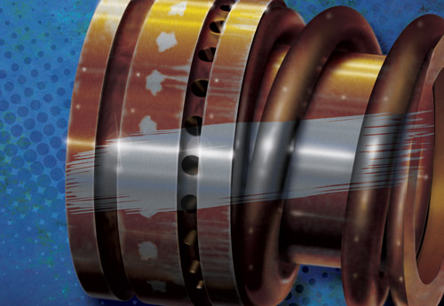
Lubricant condition monitoring involves obtaining data that supports an evaluation of the acceptability of the machine performance and the viability of the oil. To date, deposits on lubricated equipment have been the focus with regards to the detrimental effects of varnish. Figure 1 shows examples of bearings with significant varnish accumulation.

In general, the alarm and action criteria used within industry are set at levels to avoid power loss or machinery damage but may not include the prevention of varnish deposits. This discounts the effect varnish has on the design and performance of the oil and may allow oil to remain in service when it has exceeded failure criteria.

A principal area of lubricant condition monitoring that can often be overlooked is the suitability for continued use of the oil. This type of monitoring determines if the oil is able to meet its design properties. When outside of these criteria, the oil can be considered to be in a failure mode. Unfortunately, this aspect of lubricant condition monitoring appears to have become lost in comparison to the significant machinery impacts seen when varnish is found in turbine systems.


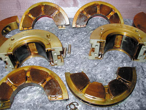
Figure 1. These heavy varnish deposits
were found on bearing surfaces.
(Courtesy Fluitec International)

If oil condition was the focus of monitoring rather than machine condition, then varnish likely would not progress to the point of accumulation and the oil would be much more capable of meeting its design. This type of lubricant condition monitoring should be emphasized when performing varnish-related monitoring since oil with a high varnish load can be expected to have critical loss in key design characteristics such as water separability and inhibiting corrosion/rust, foam and air release. Loss of any of these properties can place the system at significant risk. Testing criteria that focus on these properties should be at the forefront of the varnish issue.

Varnish Basics

The typical varnish progression begins with a reaction at the molecular level. This generally includes an oxygen molecule. In oil, the oxidized molecule is controlled through additives, which inhibit it from accelerating the degradation of the remaining oil. As more varnish forms, it becomes distinct particles that can be measured in nanometer-sized particles. As the numbers of these particles increase, this degradation material within the oil can be described as a varnish cloud of nanometer-sized material. When the cloud density oversaturates the oil, some of the varnish material will settle out within the lubrication system (like rain falling from the sky) in the form of a deposit. In time, the deposit can harden into a solid material, which is commonly known as varnish.

Oil Saturation

Turbine oil is designed to hold and manage a finite volume of varnish material. When this capacity is exceeded, the oil is considered saturated. Deposits can then form and accumulate in the system. Saturation has a relationship with temperature in that oil at a higher temperature is able to retain a greater volume of the nanometer-sized varnish material than oil at a lower temperature.


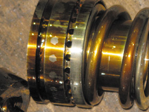
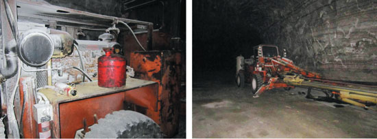
Figure 2. Varnish can occur in any system.
(Courtesy Paul Sly, Chevron)
The desired system condition for new oil would be to install the oil into a clean system so the progression of oil degradation and subsequent varnish accumulation would be limited to natural degradation of the oil. This degradation progression should be limited to the influences of new varnish created within the system as opposed to existing system varnish, which is known to accelerate oil oxidation.

It is important to install oil into a clean system so the maintenance sensitivity will more appropriately respond to the oil’s initial varnish saturation level as an oil failure criterion. This sensitivity should be maintained at the lowest expected system oil temperature rather than at a higher temperature, since deposits will form and collect in a system at this lower temperature, and deposit formation should be considered a lubricant failure mode.

Base Oil Influence

Varnish accumulation is also influenced by the base oil category, as designated by the American Petroleum Institute (API). Group II base oils have a superior design and can be expected to provide improved performance over Group I base oils, assuming that the system in which the oil is installed is clean. Both Group I and II base oils have inherent solvency, which means that they have a finite capacity to accumulate and hold varnish products. However, there is an important difference in how each does this. Due to the manufacturing process resulting in a more highly saturated molecule, Group II oils have less varnish-retention capacity than Group I oils. As such, Group II oils allow varnish deposits within a system to occur with a lower overall volume of the material present.

System Cleanliness

When a new charge of turbine oil is installed, it is vital that the system be clean and free of varnish. A common problem is that many existing systems are not cleaned prior to the installation of new/replacement oil. As mentioned previously, turbine oil has a natural design property that allows it to hold and accumulate varnish. In addition, existing system sludge and varnish that have adhered to surfaces within a turbine oil system are not readily dislodged with a system flush. As a result, when new, clean oil encounters this existing varnish within a system, it begins to chemically react with the varnish and remove this material from the walls, causing the new oil to approach a point of saturation.


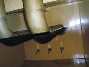
Figure 3. Varnish deposits were
found within this system.
Within a relatively short period of time, this “chemical cleaning” phenomenon can render the benefits of a new oil change moot in terms of oil performance and design. In other words, the removal of system varnish may reduce the new oil to a “failed oil” status not long after it is placed in service.

The same condition occurs after a varnish-saturated oil is cleaned of varnish residue, but the cleaning is stopped prior to the system itself becoming clean. The newly cleaned oil will again accumulate varnish materials from the system to once again approach saturation levels. Remember, varnish acts as a catalyst to speed oil and additive degradation. As such, operating with varnish within the oil allows new varnish to form more quickly and shortens the service life of the oil.

Complications/Variations

The consequences of accumulated varnish within a turbine system can include power de-rating and damage to the operating equipment. When observed problems begin to occur, the concentration of varnish within the oil or system can vary greatly. Factors such as system design, variations in the system operating temperature and fluctuations in the system operating conditions all affect varnish formation.

Systems that use turbine oil as control oil are highly susceptible to issues. The control systems include tight orifices located in lower temperature regions. These conditions allow hot, saturated oil to accumulate deposits at these important system locations.

The choice of oil also impacts the rate of varnish generation and accumulation, as some oils are more prone to varnish drop-out than others. Figure 4 shows two samples with similar laboratory settling times. While these oils have a highly similar visual appearance, they have dramatically differing levels of varnish load, which is related to the influence of oil additives, base oil and the chosen formulation.


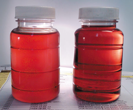
Figure 4. Different oil formulations can have very different
varnish conditions but appear highly similar.
(Courtesy Dave Wooton, Wooton Consulting)

Oils from different manufacturers are known to have different additives and base oils. Depending on the in-service operations, their differences can influence the severity of a developing varnish issue. Because these oil design variations are considered proprietary information by the lubricant manufacturers, the consumer of the oil is unlikely to be able to determine which oil formulation is least likely to cause varnish problems.

When system contaminants mix with the oil in service and further degrade it, the design properties such as water separation, foaming and the oil oxidation rate may be greatly compromised. As system design and operating conditions also vary, their impact should be considered as it relates to the select formula as well. This parameter of additive chemistry adds to existing varnish challenges for both oil performance and service life.

Laboratory Testing

The lubricant condition-monitoring community has developed a laboratory test (ASTM D7843) to assess the degree of accumulated varnish load within in-service oil. This Membrane Patch Colorimetry (MPC) test measures the overall load of varnish type material in the oil sample and includes a three-day settling period to allow varnish material to agglomerate within the oil, which is cooling from its operating temperature.

The oil is then filtered through a 0.45-micron cellulose patch with the aid of a solvent. Varnish material collects and deposits on the patch. The patch is checked for color, which is influenced by the volume of material deposited. A dark brown color is visible when more varnish from the fluid is on the patch surface.


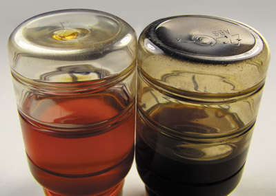
Figure 5. The MPC test measurement of the sample on the
left was 24, while the sample on the right measured 156.
(Courtesy Dave Wooton, Wooton Counsulting)

Figure 5 shows side-by-side examples of a split sample of turbine oil that was allowed to sit for a two-week settling time under controlled conditions. The sample on the left was stored in the dark, while the sample on the right was left in the sun. The contribution of the sun is the difference in these samples, which have different colors and very different varnish loads.

Alarm Limits and Criteria

The lubricant test community is currently using various versions of the color patch test to assess the volume of varnish within oil and the likelihood of damaging deposits occurring. Unfortunately, the test variations in use may scale the color differently and provide differing warning and alarm limits. These differences can lead to significant confusion in the marketplace.

In addition, current alarm limits and action criteria focus on the effect of varnish accumulation on lubricated machinery. This approach discounts the impact of varnish on the design and function of the oil as well as the potential effect of this material on other oil failure modes.

3days of settling is included in a Membrane Patch Colorimetry (MPC) test to allow varnish material to agglomerate within the oil, which is cooling from its operating temperature.

A more fundamental approach to setting alarm and action limits that includes the impact of varnish on the oil’s performance is needed. The criteria should consider when the oil has lost its design performance, and these performance failure modes should be the point of initial action.

A temperature limit of oil saturation could become an important criterion. This could be measured by the patch test but at lower limits than those presently used in order to avoid machinery issues. This approach could then retain the present criteria as a higher severity warning for varnish and separate criteria for its potential challenge to machine operation.

Mitigation

Since oil that is in operation at a fully saturated level can be expected to leave varnish deposits, mitigation strategies to manage this condition should be directed at keeping varnish levels at a concentration where deposits would not be expected to form. The following are viable preventive maintenance strategies that have been demonstrated to benefit the system oil condition or varnish saturation level:

Partial or Full Oil Changes

As new oil does not have any retained varnish products, it would not be expected to cause new deposits when added to the system. However, the benefit of this method is severely limited by the quantity of varnish deposits within the system. When new (or newly cleaned) oil is placed in service, its inherent design results in cleaning the existing system varnish, which then goes into the oil. After this has occurred, the oil can again become saturated, and new varnish deposits can commence once saturation levels have been reached.

A secondary problem can develop from this mitigation strategy if varnish is removed from a less harmful area and then re-deposited in more undesirable locations. Another drawback in making frequent oil additions including full oil replacement involves the expense, as large volumes of oil can be costly.

While this approach could be beneficial if implemented in a manner that keeps the oil in a less than saturated condition, managing this would require frequent laboratory tests to ensure the oil condition. It is also questionable whether oil consumers would be sufficiently sensitive to the rate of varnish accumulation or change in the new oil to properly implement this method. However, it would produce a net benefit if performed periodically, as the cleanliness of the system in terms of existing varnish deposits can be improved with time.

Filtration with Cellulose Media

The best time to filter varnish material retained within oil is when the oil is at an ambient temperature for a few days. This allows the varnish to agglomerate and be collected by the filter material. Filter replacement is a must if this strategy is employed, as varnish material removed from the oil at ambient temperature returns to solution if the filter is not replaced prior to returning the oil to the higher operating temperature. This is due to the greater solvency of the oil at the higher operating temperature.

The primary limitation of this approach is that the filtration is limited to the reservoir oil and cannot be expected to reduce the volume of varnish within the main turbine system. When the oil returns to service, its inherent design is as a solvent, thus the results are removal of system varnish. Once again, due to existing system deposits, a saturation of the operating oil can reoccur.

In addition, varnish can migrate from a less harmful area to an undesirable location. The overall cost of this strategy can also be expensive, as frequent filter replacements could be required to remove system varnish from the varnish-laden filters. However, this method does produce a net benefit when performed periodically, and the cleanliness of the system in terms of varnish deposits can be improved.

System Chemical Cleaning

This method is the quickest way to improve system cleanliness and allow the oil to function as it was designed. While a clean system will extend the useful service of the new replacement oil, it cannot be expected to prevent reoccurrence of varnish. Its cost to implement can also be high.

Ion Filtration

With ion filtration, oil is processed through resin beads, which chemically attract the varnish component and remove it from the oil. This cleaning can occur at operating temperature. Ion filtration takes advantage of the oil’s design to slowly clean and remove existing varnish from the system as the oil is in service. With time, this process produces both a clean system and clean oil.

Conclusion

Mitigation strategies of ambient temperature filtration followed by filter replacement or installation of new oils can be used to manage varnish in systems if carefully employed. Of course, these strategies will carry the cost of additional oil and filter purchases. Regular laboratory testing also would be needed to manage these strategies and to monitor their effectiveness.

The introduction of Group II base oils as a fundamental component of turbine oils has not caused the varnish issues that plants are currently encountering, although their solvency and capacity to hold varnish were contributing factors. The change to a Group II base oil component has reduced the capacity of the fluid to retain varnish materials. Additional contributors include the formulation of the oil, the system design, the operating conditions and how much existing varnish is within the system.

81%of lubrication professionals have experienced problems caused by oil degradation products such as varnish and oxidation, according to a recent poll at machinerylubrication.com

A primary culprit of varnish problems occurring within industry can be directly attributed to the system cleanliness in terms of residual varnish deposits. The key to long-term varnish mitigation is in establishing a system free of varnish and then continuing a process that maintains both the oil and system in this condition. Ion filtration has been demonstrated to create these conditions, although once the system is clean, frequent oil additions or filter replacements may also be useful.

While the current industry focus regarding varnish has been on turbines, the same base oils and formulations are used for compressor, circulating and large motor/gearcase applications. Likewise, the same degradation mechanisms of the oil and additives would be present with subsequent varnish accumulations expected to occur. Such varnish deposits may be found on bearing and gear surfaces as well. Although the consequences of this accumulation and stress on oil properties have not been discussed, sensitivity to varnish should also be applied to these applications.

Alarm and action limits should be established to ensure system and oil cleanliness. This approach is challenged by long-standing plant operating expectations and experiences where varnish sensitivity was not required. The existing belief that there is an acceptable quantity of varnish within either the oil or system and that it is of no consequence must be overcome. Low action and alarm criteria should be set to protect the design and performance of the oil. In other words, a no-tolerance approach to varnish is required.

Monday, 19 September 2016

Secrets to Becoming a World-class PM Facility

Article extract from ReliablePlant newsletter:
http://www.machinerylubrication.com/Read/29221/world-class-pm-facility


A team effort at Cargill’s salt mine leads to reliability excellence.

The primary goal in any industry is maintaining safe, reliable equipment. This involves getting the maximum uptime at the lowest cost of operation and extending the as-designed usable life. The fundamental cornerstone of this proposition is effective lubrication in concert with preventive and predictive maintenance tasks that are carried out in a quality manner.

Performing required lubrication in a proper manner is challenging in even the best conditions, but at Cargill Deicing Technology’s rock salt mine in Cleveland, Ohio, the obstacles were considerable. The mine is 1,800 feet deep and extends approximately 4 miles under Lake Erie. The underground mining operation utilizes a room-and-pillar style of mining, and its business is dependent on Mother Nature, since the primary product is deicing salt used for keeping roadways and sidewalks ice-free.

The mine maintains a fleet of specialized mobile equipment that extracts the salt, which is transported on a conveyor system to the milling operation and then hoisted to the surface for distribution. Diesel-powered mobile equipment is used for the extraction process. These machines are high oil consumers that require 250-hour operational oil changes.


Cargill Deicing Technology’s rock salt mine in Cleveland, Ohio, is 1,800 feet deep and
extends approximately 4 miles under Lake Erie.

The maintenance team made best-practice theories a reality by constructing a world-class, all-inclusive preventive maintenance (PM) facility, which is a unique installation for any underground mine. Considering all the challenges they had to overcome, the employees rose to meet and overcome those problems with very successful results, thanks in large part to having an engaged workforce and proper training.

Old Practices

Approximately 10 years ago, the mining operation performed equipment servicing and PMs where the equipment was parked. All the material was brought to the machines, including filters, oils, drain pans, supplies, etc. Oil was transported in generic cans that were filled at a bulk station. The top of the can and equipment fill point were wiped off to keep dirt out when new oil was added to the machine. Waste oil was collected and poured back into the same cans to be dumped in the bulk waste-oil container, which was sent back to the surface for recycling.


Previously, Cargill performed equipment servicing and preventive maintenance where the
equipment was parked. Oil was transported in generic cans that were filled at a bulk station.

Oil samples were taken, but maintenance personnel didn’t understand the value, since they did not receive any feedback and no actions were generated as a result of the samples. Once the oils were drained, there was an ongoing question of what product should be used for refilling.

Beginning the Improvement Process

With so many issues at the mine needing improvement, the question was where to begin. It was determined that the best starting point would be to develop the knowledge base of the maintenance personnel. Part of this development was to have each mechanic attend a three-day lubrication course, which was conducted onsite. This helped provide the fundamental understanding that every component requiring lubrication needs the correct lubricant applied in the correct manner in the correct amount at the correct time. When these four principles are followed, equipment can last almost indefinitely.


Cargill maintains a fleet of specialized mobile
equipment that extracts salt from the mine.
Of course, acceptance is not always easy when conducting this type of training with long-time employees. About a week after the training, one veteran mechanic requested a lubricant specification book because he believed an incorrect lubricant was being used for an application. This was a major accomplishment. Having a highly seasoned employee requesting clarification meant he not only understood the class, but he also was applying what he had learned. This was a good first step.

Creating a New PM Bay

With a workforce that is engaged, employees execute what they learn when they understand why. Maintenance personnel soon began questioning current practices and believed they could make improvements, such as building a PM bay. Working with a maintenance supervisor, they decided what should be included in this area. They wanted to be able to perform PM inspections and kidney-loop filtration of systems, not just service equipment.

With a plan in mind, the team started assembling the necessary components. A location near the shop was designated as the PM bay area, and construction soon began. Once completed, the PM bay featured all the necessities for oil storage, pumping and filtration. Safety items were added such as an overhead fall-protection restraint system when accessing the top of the equipment.


Salt is loaded onto a conveyor system for transfer to the milling operation, which crushes
and screens the salt into a usable product before transporting it to the surface.

As the PM bay was put into use, employees became proud of their accomplishment. Although it was not much to look at, it was a major upgrade from what they had been doing. Functionally, the PM bay achieved its intended design of supplying clean, filtered oil to the equipment. More importantly, the improvement came from the workforce wanting to be more proficient. This created a culture shift. Performing PMs where the equipment was located became a thing of the past. Everything now came back to the PM bay, and workers performed PMs with greater care, which translated into better equipment availability.

Continuing to Improve

Mining is an ever-moving operation. As the mineral is extracted, the distance from any permanent location increases. Soon, the PM bay became one of those locations getting farther away. Moving equipment to the bay took longer, leaving less actual PM time.

A suggestion was made to move the PM bay closer to the working face, which would mean more time with the equipment. This was a great idea, but it was a monumental task to disassemble the current PM bay and reassemble it in a new location while managing the required day-to-day maintenance activities.

Then a question was asked: “What if the PM bay was portable so it could continually advance with the faces?” This began a quest to find a supplier that could build a rugged, portable lubrication containment for an underground mine.

Employee involvement was critical. The site lubrication team, mechanics and maintenance apprentices who performed the equipment PMs were asked what they would like to see in this portable lubrication containment. Some of the suggestions were:

  • Hose reels on all oil products
  • Hose reels inside but nozzles outside the containment
  • Everything pneumatically operated (no electric pumps)
  • Waste-oil pump to be high volume and discharge into waste-oil container
  • One waste-oil container outside each containment with easy change-out
  • Kidney-loop filtration built in with quick disconnects
  • Filters to include bypass indicators
  • All filters and pumps the same
  • 110-volt receptacles inside and outside
  • Internal lighting
  • A desktop area inside to complete paperwork
  • A fold-down desk area outside for diesel particulate matter (DPM) testing
  • Storage cabinet for additional filters, tools, test equipment, etc.
  • High-volume compressor to clean out radiators
  • Air hose reels in both containments with 100-foot air line
  • An additional tank and pump in each containment for future expansion
  • Runners underneath containment to facilitate easier moving over rough terrain
When the completed drawings were presented to the lubrication team, mechanics and apprentices, they were pleased everything was included and made only a few suggestions for improvements. This core group was truly engaged in the process. They made a difference, and their ideas were put into practice. They now not only had ownership of the lubrication containment but also enthusiasm in how they performed their work.


Combined employee ideas culminated in the creation of a new PM facility, which
featured all the necessities for oil storage, pumping and filtration.

This enthusiasm was contagious, as others started making suggestions on how to improve the PM process. One idea was to have a level concrete pad on which to park the equipment when doing PMs. This would allow for proper oil fill levels and provide safer footing around the equipment.

Another suggestion was to wash the equipment close to the PM bay in order to eliminate travel time. This posed several challenges, since water dissolves salt and keeping the PM area clean was a priority. One individual’s solution was to create a concrete-lined sump to catch all waste water from the washing process for recycling. This used water would be pumped into a containment tank to water roadways for dust control and improve ventilation.

These combined employee ideas culminated into making the PM facility. The entire 40-by-160-foot work area was made of concrete, creating a safer work environment and improving PM quality. However, this was a major undertaking and required a lot of hard work. The concrete had to be lowered underground, transported to the site as a dry mix, mixed onsite, poured and finished by a crew of volunteers from the maintenance team. This illustrated their belief in the project and their commitment to making their ideas become a reality.


A portable kidney-loop filtration unit was designed
to meet the needs of the mining operation.
When mobile equipment is scheduled for a PM, it is now brought to this new facility. The equipment is first washed and moved 80 feet for lubrication servicing. PM inspections are then conducted on the clean equipment. Predictive tasks like oil sampling are performed using proper procedures and sample ports, and exhaust emission testing is completed. All issues that are discovered in the inspections are noted with a follow-up work order to repair or investigate the problem.

New Practices

Two lubrication containments are used in the new PM facility, with one for general oil and one for equipment-specific oils. Dispensing nozzles are labeled and color-coded. Hose reels are used for all oil, grease and compressed air. There is a drop-down work area outside for completing paperwork or holding test equipment. Tanks are identified by name with color-coded labels. This minimizes the chance of filling a tank or dispensing the incorrect product where it does not belong. Each tank also has its own desiccant breather attached. There’s even a flat surface for completing paperwork.

New oil is filtered with 10-micron, Beta-1,000 filters when it is transferred into the storage tanks from sealed 5-gallon cans. The oil is again filtered upon dispensing to ensure the cleanest oil goes into the equipment. All filters are equipped with a go/no-go filter bypass indicator. When the needle is in the green area, the filter is operating. When filters are in the red section, it’s time to stop and change the filter. This condition-based strategy of filter replacement maintains oil cleanliness while maximizing filter life to reduce cost.

Each unit has a waste-oil pump that is plumbed to a 300-gallon waste-oil tank, which is behind the containment for easy replacement. One unit is equipped with a kidney-loop filtration system using the 10-micron, Beta-1,000 filters set up in a series with quick disconnects. Both units have pneumatic grease guns and fire-suppression systems that are sensor-activated.

Lubricant Consolidation

After examining its underground lubrication inventory, which was in excess of 60 different lubricants with several very similar products, the mining operation initiated a consolidation effort. With the assistance of the lubricant provider, the team evaluated each application for correct product specifications and was able to consolidate down to 10 oil products and two grease products for mobile equipment plus an additional six oil products and one grease product to cover all rotating stationary equipment.

A product application sheet for mobile and rotating stationary equipment was then developed. This color-coded, one-page sheet listed all mobile or stationary equipment and identified the product to use in each application. This significantly reduced inventory and cross-contamination while providing a quick reference for application. Without this consolidation effort, it would have been nearly impossible to build a lubrication containment with enough capacity to house all the different oils.

The Importance of Training

Although the mine’s maintenance personnel generally filled the equipment and gearcases, operators would top-off equipment when they performed a preoperational inspection and found a low oil level. Therefore, to make sure anyone adding oil to the equipment understood the consequences of their actions, lubrication training for some equipment operators and storeroom personnel was implemented.

It Takes Time

When attempting to become a world-class PM facility, it’s important to understand that improvements will not be immediate. They cannot be measured on this month’s metrics sheets or even in this quarter’s results. There must be a vision where progress is compared by years.

Failures will not disappear overnight. Those failures are a direct function of current condition over time. Cleaner oil cannot compensate for a worn gear, bearing or pump but may decrease further damage.

Early on, oil analysis may show a multitude of issues where you lose faith in the process. When components are rebuilt or changed, slowly you will see a trend of improvement. This requires determination and discipline to stay on course, especially when it seems easier to abandon the initiative.

Reject the short-term view in favor of a long-term vision. For instance, if a new hydraulic pump with dirty oil can last six months, using clean oil and a long-term strategy may allow the new pump to continue efficient operation for five years, saving the cost and time of nine pump changes.

Upon completing the training, one operator said he didn’t know oil was that important. He had been adding the wrong oil to his transmission. This showed he wanted to do the right thing but just did not understand why.

Storeroom personnel were trained in lubrication practices because they were the first line of defense in ensuring the correct oil was being put into a machine. Before the training, when someone requested oil, storeroom personnel would fill the request. After the training, an oil request was met with the question of where was the oil going to be used. If the oil requested did not match the application, storeroom personnel would explain that was the wrong oil and then provide the correct oil. This was a great start to control cross-contamination and educate employees.

The lubrication training also taught personnel the value of oil analysis and how to take proper samples. The goal was to make the oil analysis information meaningful. Each sample result would be reviewed when the lab report was received by email. Follow-up work orders would be written to address any anomalies. The results would be posted for all personnel to review. The lab would maintain a database on its Website of all current and historical analysis reports by machine number. Every maintenance employee would have the Web address, username and password with access from any work or home computer. This has made a significant improvement.

Measuring Progress

The Cleveland mining operation has invested a considerable amount of time, money and manpower into improving its lubrication standards and developing a world-class PM facility. Was it worth it? The team is effectively trying to measure the impact by determining how many issues were prevented. Within the first month of operation, the identification and documentation of potential problems by craftsmen completing PMs increased 30 percent.

Many of these described initiatives have reduced cost, improved equipment availability and increased productivity. However, while some things can be measured mathematically, others are not as obvious. For example, consider the direct effect an engaged workforce has on the results. Having the most technologically advanced systems will not necessarily gain improvements without a workforce taking ownership and pride in their accomplishments. This highly skilled and engaged workforce knew how to work as a cohesive team to foster successful results.


When mobile equipment is scheduled for a PM,
it is brought to the new PM facility, where it is
first washed and then moved 80 feet for lubrication
servicing. PM inspections are then conducted
on the clean equipment

The old adage that grease is grease and oil is oil may have worked 50 years ago but no longer applies. Personnel must develop a healthy respect for the complexities involved with proper lubrication practices. The basics of workforce development can be achieved through education and training, while the willingness to execute will be anchored in engagement.

The Cleveland mine has taken a significant step in maintaining its mobile equipment fleet in the safest, most reliable condition with the development, construction and implementation of a world-class PM facility. This was a tremendous team effort in the quest for reliability excellence.

Tuesday, 16 August 2016

Best Ways to Prevent Equipment Problems

Article extract from MachineryLubrication newsletter:
http://www.machinerylubrication.com/Read/30560/prevent-equipment-problems


Preventive maintenance methods are often promoted but rarely put into practice. This article will attempt to encourage a paradigm shift in maintenance thinking with prevention driving most of the activities. The main thrust will be on leadership and not 
simply management.


Leadership vs. Management


The classic definition of management is to do things right. The definition of leadership is to do the right things. The difference may be subtle but very important. How often have you witnessed someone planning a repair job to be completed within an allotted timeframe when no one was asking why this repair needed to be made so frequently? 


A manager attempts to get work done on time, while a leader attempts to minimize or eliminate the required work. A manager continually asks for more people, while a leader tries to maximize the effectiveness of his or her staff. A manager tackles problems as they arrive, while a leader asks why continual problems are tolerated.


Prevention Depends 
on Leadership


Without proper leadership, problem prevention is very difficult to achieve. The following case studies illustrate a variety of situations in which preventive techniques were used effectively in a typical mill environment.


A Poorly Designed 
Hydraulic System 


In this mill, steel slabs issuing from a caster started as a long, continuous hot metal strand. A torch cutter sliced off 30-foot slabs from the front end as the strand moved at a slow pace. The slabs were lifted off the table rolls and stacked for delivery to a storage yard by a carrier. The tongs resembled two pairs of giant 10-foot scissors operated by hydraulic cylinders and fed by a hydraulic system mounted near the top of the scissor arms. The system had a vertical tank with a pump mounted beside it. Due to space limitations, the valves, tubing and hoses were located directly over the pump and motor, making for a very congested design. The entire assembly hung from a crane. When an O-ring blew or a valve needed changing, quite a bit of disassembly was required to access the bad part. A lot of time was also wasted with repairs on this equipment due to the design.


The cause of the problem was obvious, and only a redesign would suffice. The supplier of the tongs was contacted and told the system design was inadequate. With “manifolding” technology, much of the pipe, tubing and hoses could be eliminated as well as the congestion in the confined spaces. The supplier agreed to redesign this part of the system, which solved the problem. This case exemplified a unique issue where only prevention of future problems would suffice. Learning to live with the problem was not an option.


Inefficient Purchasing 
of Lubricants


At this particular company, lubricants and hydraulic fluids were purchased by individual departments with no coordination between them. Consequently, the number of brands proliferated, increasing the chances of duplication. Products were procured by brand name, and the purchasing department had no choice but to buy what was requested. Because lubricants were purchased by brand name with no competition, suspicions arose that prices might be excessive. When a problem arose, quality was blamed and another supplier was brought in to solve it.


It was suspected that the company was living with a problem that could be resolved. Because ASTM and other test methods could help determine product quality, a committee was formed to decide how to purchase lubricants based on these tests. A strategy was soon developed. All products would be tested for important parameters to uncover duplicates. Products would be separated by categories such as petroleum hydraulic fluids, fire-resistant hydraulic fluids, general-purpose greases, electric-motor bearing greases, petroleum turbine oils, gear oils, anti-friction bearing oils, petroleum circulating oils and synthetic oils.


Specifications were also written for each lubricant type based on the test results of the higher grades in each category. Every specification was assigned a unique number, and equipment throughout the plant was tagged with the number of the product it was 
to receive.


The specifications were sent out for bids from various suppliers. The lowest bidder was awarded the business for one year. The prices received were markedly lower than the comparable branded products.


After the initial groundwork was completed, the system began to function well. The inventory shrank because so many locations used the same products. Purchasing in bulk became possible due to consolidation, which also resulted in a reduction in drums and costs. Samples of incoming products were taken periodically to ensure quality. Gradually, the overall quality improved. 


The goal of the system was to purchase high-quality products at the least possible cost and to eliminate as many empty drums as possible. Mistakes related to applying the wrong lubricant were also reduced. Once the system was in place, it took very little time to maintain it. 


This was an example of a plant living with a problem that not many thought was a problem. It was only after some penetrating questions were asked that most were convinced that there might be a better way of doing things. How the plant was purchasing lubricants was costing much more than necessary both in dollars and in manpower.


Short Motor Bearing Life


In this hot mill, as the steel strand issues from the last finishing stand, a long series of rolls conveys it at high speed to the coilers. Each roll is individually driven by an electric motor. Water cascades down from sprays to cool the strip as it speeds toward the coilers. Despite elaborate splash guards, it is almost impossible to keep water off the motor shafts. The shaft seals were not adequate to keep water out of the motors, and trying different seal designs did not help. The motor repair shop could barely keep up with all the failures. Finally, a seal company recommended adding flingers on the shaft. These consisted of a rubber device that looked much like a shaft seal but with a hole in the center slightly smaller than the shaft diameter. As a motor was repaired and ready to ship, the repairman would slip a flinger onto the shaft up to the housing. When the motor was installed in this wet environment, any water that migrated toward the seal area would be flung off due to the rotating flinger. In this way, water could not get to the seal. Motor bearing life increased tremendously. In this instance, a serious problem was prevented with a simple device but only after someone asked why this was being tolerated.


Frequent Servo-valve Repairs


As steel mill technology improved, more and more servo valves were being used on the mill’s hydraulic systems to gain precision. Because of dirt sensitivity, systems with servo valves must be filtered to extreme cleanliness. Despite great efforts, servo-valve losses were becoming excessive at the mill. Costs were also high since the repairs could not be done in-house. 


To prevent these failures, a non-bypass duplex filter separated by a three-way valve with an electrical alarm was installed ahead of each valve. The filters had a cleanliness level of 1 to 2 microns. When the alarm sounded, maintenance personnel knew they had only a few minutes to switch the three-way valve to the clean side before a shutdown occurred. A clean filter element was always on standby. The result was that the servo-valve failures virtually ceased.


Once again, a simple design change prevented a serious problem. However, the difference with the servo-valve issue was that production was being affected as well as repair costs.


Excessive Oil Losses


Oil losses were becoming excessive in the mill’s hydraulic and lubrication systems. The millwrights dutifully kept the systems filled and operating but did not report all the oil additions as they were made. When additions were reported, there was no good method for determining the amount. Therefore, it was difficult to establish where the bad leaks were and to schedule repairs. Prevention or reduction of these oil losses was the goal, but they could only be attacked when they occurred.


The decision was made to mount small water meters on the fill lines to each system. These meters had some internal friction, but since the oil was being pumped in as makeup oil, the pressure required was adequate. In cases where the oil flowed by gravity from an upper to a lower floor, low-friction meters were required. Each day, an inspector read the meters to determine if any leaks had gone unreported. If so, action was taken. This was an example of taking preventive action (reading the meters) to prevent further losses. No action could be taken without proper information supplied by the meters.


Rapid Motor Burnouts


The plant’s coke oven doors are approximately 20 feet tall and 4 feet wide. They are made of steel, lined with firebrick and weigh about 1,000 pounds. Each is mounted vertically on each end of the oven and must be lifted off by a huge machine so the red-hot coke can be pushed out. The doors are held in place by two steel arms that are rotated into place behind vertical “buckstays.” In the center of the arms is a hexagonal nut that is 5 inches in diameter. The arms are rotated by a large socket that fits the hexagonal nut and is operated by a motor and gear reducer mounted on the machine. The arms often become wedged behind the buckstays, so an electrician must hold in the overload relays to get the motor to turn. Frequent motor burnouts were attributed to this practice. 


Rather than increase the size of the motors, the decision was made to convert the operation to hydraulic motors due to the inherent overload protection in such a system. Relief-valve adjustment serves this purpose.


Because of the large amount of dirt inherent in the coke plant and the dirt sensitivity of the hydraulic motors, the hydraulic systems were redesigned. This redesign was so successful that no hydraulic motor failures occurred for the first five years. The improved cleanliness also increased pump life. This case was an example of prevention involving a radical design change with which not everyone agreed.


Unchecked Oil Temperatures


At another hot mill in the Pittsburgh area, the challenge was determining the cause of losing several back-up bearings. It seemed to be a case of the oil overheating, but when the coolers were examined, none of the thermometers was working. It also appeared that no one was checking the key system parameters, such as temperature, water content, flow, tank levels and cleanliness. 


When the thermometers were replaced, oil temperatures of 175 degrees F were observed. Evidently, the coolers were having no effect. Once the coolers were replaced, the problem ceased. 


This was a case of not paying attention to signs that can warn of impending problems. Management hastily instituted a form to be completed on each shift that forced someone to watch those important system parameters. 


Misreported Oil Demulsibility 


Oil purchased for the mill’s back-up bearing system needed to be able to drop out water quickly. The purchasing specifications gave a very strict number that had to be obtained from the ASTM D-2711 test. ASTM D-1401 is another test for demulsibility, but it is used for light oils. The heavier oils utilized for these back-up bearings had to be tested with the former test, although it took much longer than the ASTM D-1401 test. 


The mill was experiencing a rise in water levels with samples tested from new loads of oil. Samples taken from in-service oil were having the same problem. Under normal conditions, the water levels should have remained under 5 percent but were now 20 percent. The lab assured the mill that the samples of new oil were within the specification. This situation continued for several months as an investigation was conducted. There were concerns that back-up losses would soon begin rising. 


As luck would have it, the lab shut down, which meant the mill had to find another one. When the next sample was sent to the new lab, the mill immediately received a call that the demulsibility was below specification. The load had been pumped out and replaced with a load from another company. It turned out that the old lab had been using the ASTM D-1401 test because it was quicker than the D-2711 test but did not inform the mill. The oil supplier didn’t even have the equipment to perform the D-2711 test but was relying on its additive supplier to provide the percentage to use. This was a case of having all the needed tools in place but still getting bad information.


Three Phases of Prevention


These case studies encompass preventive actions for three types of situations: an obvious situation, a change of methods situation and an unseen situation. Each of these is described below.


An Obvious Situation


These situations are like the poorly designed hydraulic system or the electric motor bearing issue. The problem is very costly, and the solution is either obvious or requires a design change. The solution will also require time, money and the will to do it. Most agree that solving the problem is worth a try since it is easily seen. These situations are usually designated as “crises.” The alternative is to learn to live with the problem.


A Change of Methods Situation


These situations involve a long-standing way of doing things, such as each department buying lubricants with no attempt at consolidation or not reporting system fluid additions. Although the problems are seen, not everyone envisions a solution or agrees one is needed. Personnel have learned to live with the problem. Basically, the way things are done must be changed.


An “Unseen” Situation


Many times actions can be taken to prevent bad things from happening. These include condition monitoring, regular inspections, close monitoring of system gauges and oil sampling for laboratory tests. Every plant system has parameters that must be checked periodically. These checks consist of people making an assessment of the condition and filing accurate reports. When these people do their jobs correctly, bad things are prevented. 


Short-sighted managers only “see” the people who repair things. Those focused on prevention work in a less dramatic environment. Consequently, when the economy is poor, these jobs often are eliminated. 


Leaders not only must ensure the “seen” is handled efficiently but also that the “unseen” is not neglected. The “unseen” typically requires recognizing the indications of bad things about to happen, which can often be identified in regular inspections by sight, feel, smell or hearing. However, most of the “unseen” must be detected by equipment. This would include temperature, vibration, sound and lab tests. 


The “unseen” also involves a conviction that technology can be used to predict events in order to avoid or plan for them. This conviction is an important leadership attribute. Remember, managers don’t see the “unseen,” but leaders do.


Tuesday, 2 August 2016

Expert Tips for Planning a CMMS Project

Article extract from ReliaPlant newsletter:
http://www.reliableplant.com/Read/28932/planning-cmms-project

A well-planned and executed computerized maintenance management system (CMMS) project can yield a maximum return on your investment. This return is realized through increased efficiency, productivity and profits. However, a poorly planned and executed CMMS project can result in a loss of revenue. These losses can be measured in terms of the overall investment in the project, as well as from wasted time and lost projected revenue forecast tied to the successful installation and implementation of a CMMS.

Planning

Properly planning the CMMS implementation project is one of the key elements. In the planning phase, you determine the “what,” “why,” “who” and “how.”

Equipment Data

Developing a plan for equipment data is a good first step because it will provide a CMMS with a foundation of hard, verifiable data. Some maintenance departments may already employ an equipment numbering scheme that is effective. This can easily be translated into the CMMS. If there is no scheme currently in place or if the current one is flawed, it is time to develop an equipment numbering scheme.

Determining an equipment hierarchy is the next step. This involves setting up parent/child relationships among equipment. For example, an air handler can have pumps and motors as children. If you are going to keep track of both the parent and children, the relationship must be documented. Make sure to include every piece of equipment that falls under that hierarchy scheme. Parent/child relationships also can be constructed for whole facilities. For instance, a building could be the parent with each floor a child. Each room could then be a child of the floor.

Information on spare parts should be tagged to the individual pieces of equipment. This is referred to as the bill of material (BOM).

Finally, you need to decide what you want from your CMMS in terms of downtime monitoring. You should choose which pieces of equipment you want to monitor as well as how you want to track planned vs. unplanned downtime. Plan based on impact or loss of operation. You should have this information for each piece of equipment or at least for critical equipment.

Preventive Maintenance

The following decisions have to be made for each preventive maintenance (PM) task:

  • Will the PM be performed by calendar time or run time (miles, hours, etc.)?
  • Will the PM follow a fixed schedule (regardless of completion date) or a schedule based on completion date?
  • How often will PM work orders be generated (daily, weekly, monthly, etc.)?
  • What are the strategies for route-based PMs? (For example, an inspection route for all fire extinguishers in a building.)

Procedures

Procedures can be preventive maintenance, safety instructions or any other set of instructions. Each piece of equipment should have identified for it all the preventive, corrective and predictive maintenance tasks necessary to properly maintain that equipment. Along with the maintenance task, information regarding maintenance frequency, responsible craft, repair and/or consumable parts necessary to compete the maintenance task, and time estimated to compete the task are some of the additional information that will enhance the usefulness of your CMMS database. These procedures can then be applied anywhere within the CMMS.

Labor

You need information on each maintenance technician such as name, address, phone, Social Security number, etc. You also have to decide if you are going to use some sort of ID card for your technicians that can be scanned by a reader. If you do, will the cards be produced in-house or by an outside vendor?

Inventory

The following actions must be taken:
First, you have to develop a part-numbering scheme. This is similar to the process used for equipment numbering. Some companies use a 20- to 30-character-long part-numbering scheme. It includes every detail of that part (i.e., type of part, thickness, diameter, location, etc.). With advances in CMMS and a field available for each of these details (category, dimensions, location, etc.), you don’t need a part-numbering scheme to include all of the details. It just increases the potential for data-entry errors.

Implicit in the development of a part-numbering scheme is the need to concretely define the details of parts. The most useful in terms of work flow is defining the location of a part. Is there one or multiple stockrooms? Is there a location scheme within the stockroom (i.e., aisle, bins, shelves, etc.)?

In the data-gathering phase, you will compile a list of all the vendors from which you buy parts and services. One of them should be assigned as a primary vendor for each part. The CMMS automatically generates purchase orders to the primary vendors. This can be changed by the users if desired.


At this stage, you have to decide the criteria for selecting a primary vendor (i.e., price, delivery, overall service, etc.). Additionally, you should track vendor/manufacturer part numbers for cross-referencing purposes. You also need to decide the issue units that you are going to use (metric, British or a combination of both). How are you going to handle inventory of pipes, beams, etc.? Are you going to keep track of lengths? If a piece is cut, are you going to keep track of the remaining pipe length? Once vendor and tracking information is decided upon, you also need to determine:

  • Who has the authority to order parts and up to what amount?
  • Beyond what amount will further approval be required?
In the overall planning of the physical inventory process, you must make the following decisions:

  • How often are you going to take the physical inventory?
  • Who is going to do it?
  • Is it going to be manual or using mobile technology? If it is manual, make sure your CMMS has the capability to print the appropriate forms for this purpose.

Associated with this step is development of a parts label design and barcode label design. What information do you want to print on the parts labels? Part number, description and location are typical. If you are using barcoding with inventory, you have to decide which information items you want barcoded. Part number and location are typical.

If you have multiple plants/facilities, it is important that every facility follows the same schemes. Without consistency, the CMMS will not be very effective. If you are looking for a part at a different facility and that facility describes the part differently than you do, you may not find it even if it is in stock.

Purchasing and Accounting

You likely will need the purchasing and accounting departments involved in the planning phase for these:

  • “Bill to” information
  • “Ship to” information
  • Sales tax rate
  • Determine budget accounts and amounts

Codes

You should determine what plan and design codes will be used throughout the CMMS. During the planning phase, you need to decide on strategies for the basis of codes. Actual compilation of codes will be done during the data-gathering phase. Determine the following:

  • Account codes
  • Work order type
  • Failure codes
  • Action codes
  • Repair codes
  • Work order priority
  • Equipment criticality
  • Work order status
  • Purchase order status
  • Departments

Mobile Applications

If you are employing mobile applications, you need to identify each application and work on articulating the details. Some examples include using a hand-held remote data-entry device to collect equipment meter readings, parts can be issued and/or returned using a hand-held device, hand-held devices can be used to count and track inventory parts, etc.

Backup

Decisions also need to be made regarding data backup. An articulated backup scheme should be formed that takes into account both hardware and setup. Determine how often backup will be done (daily, weekly, etc.).

History

Plan for the type of maintenance history you want to maintain. Your decisions should include date performed, task performed, the person(s) who performed the job, estimated and actual time to perform, equipment performed on, material used, and any outside contractor cost incurred.

Decisions

Several decisions need to be made regarding the general operation of your CMMS. These questions provide information not only for planning but also for evaluating current capabilities:

  • Are you going to print estimated time on work orders?
  • What details of reports are needed in your CMMS?
  • Which reports are needed in graphics format?
  • What decisions will be made based on reports analysis?
  • Security issues: Who is permitted to do what?
  • Field legends: Do you need to change the terms provided by your CMMS on any of the legends? If yes, be sure to document the changes.

Key Performance Indicators (KPIs)

Develop a list of KPIs for your application. At this stage, you should review them and revise, if necessary. Also, determine how you would compute those KPIs. Most of the KPIs should come from CMMS reporting.

Assign Responsibilities

Plan on who will:

  • Install the hardware (if necessary)
  • Maintain the computer hardware, backups, etc.
  • Perform archiving and merging of data
  • Take care of disaster recovery
  • Generate reports
  • Review and analyze various reports
  • Plan and schedule work orders
  • Do the ongoing data entry
  • Close work orders
  • Be responsible for customizing, configuring, tailoring and maintaining the CMMS
The planning stage of a CMMS is perhaps one of the most important in ensuring success. Granted, implementation itself is not a short process, but with a well-laid-out plan where all possibilities are considered, the process will be simpler and streamlined.

The major challenge in planning a CMMS is considering the entire breadth of your operation down to every last piece of equipment, part and facility, and then remaining realistic with your goals. Consider the abilities of your operation to adapt to a new technology in a manner that will not unduly disrupt workflow. With a laid-out plan, you will reap the rewards for many years.


About the Author
Kris Bagadia is the founder and president of PEAK Industrial Solutions. He has experience in all facets of the maintenance management process and has stayed at the forefront of CMMS/EAM technology ...