Monday 22 April 2013

Managing the use of Extreme Pressure (EP) Oil Additives

Article extract from Reliable Plant newsletter:
http://www.machinerylubrication.com/Read/28958/ep-additives-effects

The Effects of EP Additives on Gearboxes  


Oil additives offer a wide range of benefits, but in some circumstances they can actually be harmful to the machines in which they are added. For example, let’s look at worm gearboxes. These machines have gearing composed of yellow metal (typically bronze). Certain extreme pressure (EP) additives can chemically react with these softer metals, causing premature wear and even failure.
Worm gearboxes are mainly comprised of two units: the worm and the worm wheel. The worm is what actually drives the worm wheel. It is a rod with a helical ridge on its surface that allows it to mesh with the teeth of the worm wheel to provide rotary motion.

62%of lubrication professionals use extreme pressure (EP) oils to lubricate worm gears, based on a recent survey at machinerylubrication.com

These gearboxes are great for achieving high reduction ratios as well as high torque. In order to increase either of these values, the worm wheel is made larger in diameter. The larger circumference the worm wheel has, the greater the speed reduction and the greater amount of torque will be imparted through the exit shaft.
Generally, the worm is made of steel, while the worm wheel is made of a yellow metal. However, in some cases, both the worm and worm wheel are steel, or they both may be yellow metals. The worm is always harder than the wheel.
Yellow metals, as the name suggests, are yellowish in color. They are alloys that contain copper. A standard definition would be a type of brass having about 60 percent copper and 40 percent zinc. Bronze is another type of yellow metal. These metals have been used for centuries to form gears and other components of simple machines.

Copper Strip Corrosion Test

An easy way to determine which form of sulfur is being utilized in your EP oil is to look at the results of the copper strip corrosion test (ASTM D130). In this test, a strip of copper is immersed in the fluid to be tested at 40 degrees C and again at 100 degrees C. The strip is removed after each test and checked for staining of the copper. The results range from very little to no staining (1a) all the way to very dark stains (4c). If the results are in the area of 1b to 2a, then the yellow metals in your worm gearboxes could be at risk for chemical attack.

EP additives that contain sulfur cause the most damage to these types of metals. Two different types of sulfur may be used within these additives. The first type is active sulfur. Sulfur in its active state readily reacts with metal surfaces to form a ductile metal soap that is sacrificial and allows opposing surfaces to contact one another with minimal damage. Active sulfur is chemically aggressive, and with yellow metals being softer than steel, they can begin to pit and form spalls due to this chemical attack.
Rising temperatures can increase the rate at which this reaction takes place. This is explained by the Arrhenius rate rule, which states that the rate of a chemical reaction doubles for every increase of 10 degrees C (18 degrees F) in oil operation temperature.
The second type of sulfur used within EP additives is inactive sulfur. It is less likely to bond to surfaces and react chemically.
Active sulfur in some EP additives reacts with the copper within the brass or bronze. Sulfur, when in contact with copper along with the presence of heat, forms copper sulfide. This simple chemical reaction can have devastating repercussions on the reliability of machines. In extreme pressure situations, copper disulfide can be formed. Both of these crystalline forms of copper are very hard and can cause abrasive damage to soft machine surfaces.

Worm Wheel
With all the risks associated with chemical attacks on yellow metals, why make gears using these metals in the first place? Brass and bronze are easy to machine into different shapes and yet have good strength and hardness. It all comes down to economics. When you factor in machining costs and raw materials costs, yellow metals are a very cost-effective alternative to steel.

EP additives can cause damage to a
worm wheel, which is usually bronze.
In addition, brass properties are easily changed by incorporating different metals into the metallurgy. For instance, lead can be added for enhanced machinability. For increased corrosion resistance, aluminum or tin can be added into the makeup of the alloy. The possibilities are endless for the types of alloys you can make with brass and bronze.
By understanding some simple chemistry and reading the product data sheets of the lubricants you put into your gearboxes, you can increase reliability. When adding EP oil to gearboxes containing yellow metals, remember to check the copper strip corrosion test (ASTM D130) to help predict if there will be any issues with compatibility of the metallurgy within these machines.

The "micro-skill" that drives Change in Culture

A good article from Reliable Plant newsletter in regards to Change.
http://www.reliableplant.com/Read/28886/communicating-effectively-change
Communicating Effectively During Change

I have never been known to be musically inclined, but I can recognize a great song when I hear one. One of these great songs is “I Heard It through the Grapevine.” This particular song has been recorded and re-recorded numerous times over the years by many different artists, and although it may bring thoughts of animated raisins to people in my generation, it is more closely associated with Marvin Gaye.
“Oh, I heard it through the grapevine,
Oh, and I’m just about to lose my mind,
Honey, honey, yeah.”

Just as the grapevine in this song had a strong impact, the communication grapevine remains an extremely powerful medium for corporate communications. The effectiveness of grapevine communication and its use – both intentional and unintentional – should not be ignored.
When coaching clients during major change initiatives, we continuously stress the importance of effective communication. Experience has shown that clients who struggle to communicate also struggle to successfully implement major change. Even post-project analysis of very successful projects often finds the company could have communicated more frequently and effectively at some point in the project.

One of the key success factors in successfully implementing a major change initiative is creating a comprehensive change-management strategy and then integrating it into the project-management plan. Creating a communication plan is one of the most critical elements contained within this change-management strategy. In this plan you identify target audiences, determine key messages, choose the preferred sender and select the appropriate communication channel for that message.
The majority of communication channels typically chosen are formal communication channels. The communication channel that is often forgotten is the informal communication channel, and this brings us to the topic of the infamous grapevine.

So what is the grapevine, how does it work and how can you use it to effectively communicate during major change? I am sure that the grapevine is as old as time itself, but I will discuss its context within modern organizations.

Grapevine Decoded

Every organization has both an informal and formal organizational structure as well as formal and informal communications. Simply stated, the grapevine is a type of informal communication channel. It’s all about people communicating directly with other people outside official channels of communication.

Your background and experience influence how you view concepts. For example, my background in electronics and submarine nuclear power often leads me to relate concepts to equations to enhance understanding. Personal experiences over the years related to the grapevine can also be translated and simplified into an equation to help us understand how the grapevine works. The amount of communication or “chatter” on the grapevine can be explained by the following equation:
Grapevine Chatter = Information Void + WIIFM + Recent News + Insecurity


Information Void

The laws of supply and demand apply equally to grapevine chatter and economics. An information void exists when the information demanded exceeds the information supplied. The supply and the demand of the information are not defined by the organization but by the individual person who desires the information. An information void will be filled with something – either rumors or valid information. The larger the information void, the greater the amount of chatter in the grapevine.


WIIFM

What’s in it for me (WIIFM) seems to show up in many places when we are talking about organizational change. Regardless of the situation, when change occurs our natural tendency is to translate this into a WIIFM context. This is what you are listening for. How does this change affect me, my pay, my family, my free time, etc.? Whether that WIIFM is good or bad, it creates a vested interest. When people have a vested interest, they will want information. The greater the impact on WIIFM, the greater the amount of chatter on the grapevine.

Recent News

Many organizations are stunned at how breaking news hits the grapevine at breakneck speed. Even something as simple as an office remodeling (occurring in our offices right now) can generate significant grapevine chatter. The fresher the story, the greater the chatter on the grapevine.

Insecurity

The impact of the WIIFM factor is exponentially compounded by the level of insecurity that exists. The greater the amount of insecurity that exists within the organization, the greater the amount of chatter that will exist on the grapevine. For example, with the current fragile state of the economy, one can easily see how this factor can become extremely high.

Rumors

As stated earlier, an information void will be filled. When the desire for information is high and the number of facts that are known is low, the number of rumors flying is huge. Most of us have experienced this firsthand, and sometimes it is not a pretty sight. Regaining control of information in the midst of flying rumors is extremely difficult. The longer a rumor is allowed to fly, the more difficult it is to replace it with valid information. While some people try to fight rumor with rumor, the only effective way to combat rumor is with facts. When a large number of rumors exist, an even larger number of facts must be communicated to combat the rumors.

Leveraging the Grapevine

Knowing the factors that make up grapevine chatter – information voids, WIIFM, recent news and insecurity – you can proactively intervene with frequent and effective communication. Fill information voids with accurate information before rumors materialize. Proactively communicate when breaking news is expected. When information (such as impending mergers and acquisitions) is about to be communicated, be prepared and react quickly after the message is released. When communicating change initiatives, ensure that you communicate the impact of the change on the individual.

Addressing the factors associated with grapevine chatter can minimize but never totally eliminate the amount of informal communication occurring. However, by better understanding the grapevine, you can successfully leverage it as part of your overall communication strategy.
One of the tenets of a good communication strategy is evaluating the effectiveness of your communication. This is accomplished by obtaining feedback. What better way to gather feedback than to take advantage of an existing channel of communication?

Tapping into the Grapevine

Over the course of my career, I have been able to tap into the grapevine at your typical places — the water cooler (scuttlebutt in Navy terminology), the coffee pot and the smoke break area. Tapping into the grapevine is not normally achieved overnight. Grapevine communicators are a very selective bunch. They will not share all information with everyone. There must be some level of relationship and trust established, and building relationships and trust takes time. To accomplish this, you must get out of the office, talk to people and most of all listen.

But while the traditional grapevine is thought of as being a face-to-face or oral type of communication, this is no longer the case. Advances in technology and recent trends in social networking have significantly transformed the modern grapevine. Informal communication now occurs through email, texting, Twitter and on social-networking sites such as Facebook.
Implementing major change in an organization is a complex and challenging task. In the end, creating organizational change is about cumulatively creating change in individuals. Successfully leading major change requires successfully leading individuals. To successfully lead individuals through change, you must be able to communicate effectively. You must find new ways to connect to people and communicate in every imaginable way. That includes tapping into the grapevine. Without it, you just might lose your mind. Honey, honey, yeah.

About the Author
Dave Berube, a senior consultant for Life Cycle Engineering (LCE), has more than 30 years of experience in leadership and management. His expertise includes behavioral change management, project management and development, and process improvement within various types of organizations. You can reach Dave at dberube@LCE.com.

Friday 5 April 2013

Particle Count in Oil Analysis

A good article from Reliable Plant Newsletter:
http://www.machinerylubrication.com/Read/28974/particles-friend-foe

Particles: Friend or Foe? Understanding the Value of Particles in Oil Analysis


In the field of tribology, the word “particles” means different things to different people. The following case studies illustrate how differently the mechanical engineer, tribologist, sampler, analyst and diagnostician interpret the presence of particles.

The Mechanical Engineer and Tribologist

To the mechanical engineer and tribologist, the presence of particles is an indication that contaminants have entered the system or that certain components are wearing abnormally. Particles that are smaller than the minimum clearances could result in abrasive wear, which in turn causes premature aging or failure. Large particles could result in blockages of oil channels, which could lead to oil starvation. Thus, both conditions spell trouble to these role players.


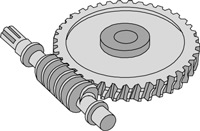
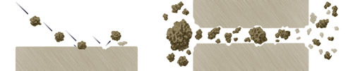
This illustration shows how particles cause damage
to parts in contact. (Ref. Triple-R Oil Cleaner)

The Sampler

The main concern of the sampler is to produce a homogenous sample that is representative of the bulk volume of oil in the system. The presence of particles complicates the task of the sampler, as particles tend to settle at the bottom of the tank/sump.
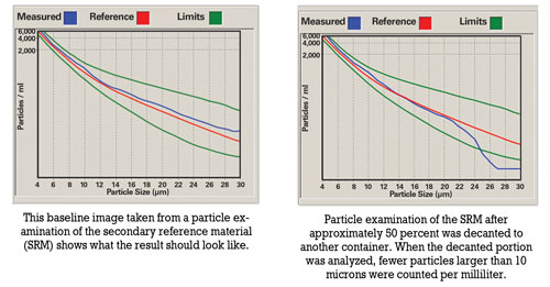
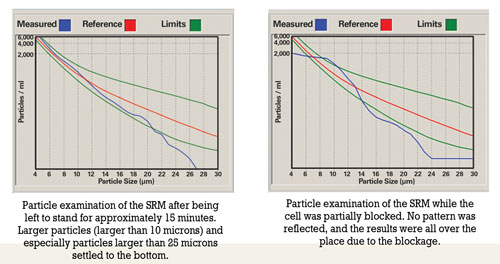
Prior to sampling, oil should be hot and well agitated to ensure that the sample includes particles that have settled. For routine oil analysis, the container must not be filled more than 80 percent to enable the laboratory to agitate the sample prior to analysis.
Improper sample handling includes overfilling containers, decanting samples that were originally filled to the top and sampling when the oil has not been circulated sufficiently prior to sampling. Overfilling a container leads to insufficient agitation. Shaking the container prior to decanting will result in large particles remaining at the bottom of the container. There’s also the possibility that the less contaminated portion is decanted, causing the laboratory result to be higher than usual.


 The Analyst

Once the samples reach the laboratory, the presence of particles directs the tasks and methods that the chemical analyst will use to analyze the samples. The method of sample preparation, the analytical techniques and instrumentation required to ensure that the results are representative of the condition existing in the application all depend on the type, size, properties and distribution of the particles present in the samples.
Various analytical techniques, including inductively coupled plasma (ICP) spectrometers, the flow cell of Fourier transform infrared (FTIR) spectrometers and some particle counters, rely on peristaltic pumps and transport systems (tubing) to introduce samples to the various instruments. When large particles are present in samples, the possibility exists that the tubing could become blocked.

68%
of machinerylubrication.com visitors view the presence of particles as a valuable indicator in an oil analysis sample

Analysts also must be aware of the tendency of particles to settle at the bottom of the container. Prior to each analysis, samples should be agitated sufficiently to ensure a homogenous state. Lowering of the fluid’s viscosity either due to fuel dilution in the engine or dilution due to analytical requirements (e.g., ICP) aggravates the tendency of particles to settle. With ICP analysis, the samples must be diluted to assist with the transportation process. Due to dilution, suspended particles are more prone to settle out on the bottom of the test tube and will not be available for analysis. However, no dilution is required with rotating disk electrode (RDE) analysis.

The Diagnostician

Particles can be of value to a diagnostician who studies the shape and nature of particles found in a sample. A scanning electron microscope (SEM) can assist in investigating the root cause of mechanical failure by allowing the diagnostician to pay special attention to evidence such as scratch marks on particles and methods of particle formation.
Fine filtration is a proactive process aimed at removing contamination and wear particles from the system. If this process is not executed with special care, knowledge and sensitivity to the value that particles add for the diagnostician in root-cause analysis, crucial evidence can be lost.

Case Study #1: RDE vs. ICP Spectrometry

In 2002 the Eskom laboratory changed from ICP to RDE spectrometry to perform wear metal analysis on used oils. To obtain a new baseline, it was essential to perform both spectrometric methods as well as the ferrous particle quantifier (PQ) on all samples received for a three-month period.
When the spectrometric results were plotted against the PQ values, it was determined that the higher the PQ value was for a sample, the greater the difference between the ICP and RDE results. For a PQ value of 15 milligrams of iron per liter (mg/l Fe), the expected difference between the two techniques was about 0 to 5 ppm. However, above a PQ value of approximately 75 mg/l Fe, the relation seemed to become non-linear, where the differences between ICP and RDE results were from 50 to more than 500 ppm.


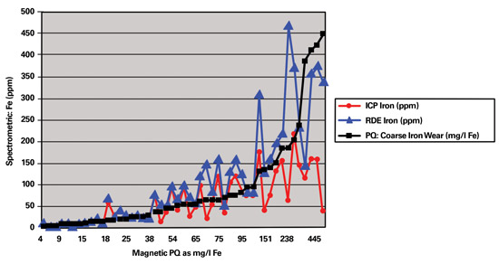
 This graph charts the relationship between RDE and ICP relative to PQ
as determined on samples of different sources.
One sample with a PQ value of 1,712 mg/l Fe had an iron value of 699 ppm with ICP. The result on the RDE for this same sample was found to be in the region of 3,000 ppm. The difference in results obtained by the two spectrometric methods was as high as 2,300 ppm.
When the wear trends of the unit with the PQ value of 1,712 mg/l Fe were examined, the ICP results gave the impression that the problem was either resolved or stabilized. However, when the RDE results became available, it was evident that there was an increase in wear. The final report recommended the unit be shut down for emergency maintenance.
Due to the lower particle size limitation of the ICP, a plateau was reached much sooner than with the RDE. Applications most affected by the ICP’s lower size limitation were those that did not have internal oil filtration systems such as gearboxes and certain compressors.
Geometry of the particles being analyzed by the RDE also affected the results. For example, if thin flakes of metal were present in the sample, flakes that had flattened out on the RDE gave a different reading than particles that had not flattened out. Thus, the results on the RDE varied due to the particle size as well as the geometry of the particles.

Case Study #2: Severe Scratching in a Locomotive Engine

The engine of a particular locomotive was replaced with a newly refurbished engine. When the engine was installed, the maintenance team had difficulty eliminating abnormal vibration in the engine. Eventually, it was determined that a bent flywheel caused the vibration.
As soon as the vibration problem was eliminated, scratching noises were audible. Everything was checked, yet the source of this noise could not be traced. The maintenance engineer decided to involve the laboratory that performed the oil monitoring program in the investigation.
Since the engine was recently refurbished and the original source was unknown, the laboratory had no history on which to base the diagnosis. To obtain more knowledge about the solid content of the oil sample, the lab employed specialized methods, such as the electron diffraction X-ray (EDX) scan technique using the SEM.
To find out if the noise was due to insufficient lubrication, the laboratory determined the oil’s viscosity. This was to establish if metal-to-metal contact had occurred as a result of the oil being too thin. A new oil sample of the specified lubricant was submitted for comparison with the oil sample taken from the engine.
A PQ analysis was then conducted to determine the magnetic property of the oil, followed by spectrometric elemental analysis using RDE spectrometry. An EDX scan using the SEM was performed on particles caught after the sample was filtered through a 0.8-micron-filter membrane and rinsed with pentane to remove oil residue.
The results revealed that the viscosity was acceptable when compared to that of the reference sample, while the PQ values were very high (more than 1,000 mg/l Fe). The RDE spectrometric analysis indicated an increase in copper, iron and zinc when compared to that of the reference sample.
The EDX scan using the SEM found the following components on the filter:
  • High occurrence of white metal bearing material
  • Metal frets
  • Iron, lead and copper shavings with scratch marks
  • Metallic iron shaving with lead bound to it
  • Zinc particles not in combination with copper
  • Mineral/rock/soil containing calcium phosphate
  • and calcium silicate
  • Silicon and aluminum silicate
  • A piece of silicone

Ionization Energy and Spectrometric Analysis

The available ionization energy to energize large particles reaches a plateau, which is one of the reasons different spectrometric methods have limitations concerning particle size (3 microns maximum for ICP and 8 to 10 microns maximum for an RDE spectrometer).
Spectrometers, as they are applied today, are blind to large particles. Traditional methods of determining large particles (larger than 10 microns) are acid digestion (expensive and hazardous), microwave digestion (expensive and time consuming) and direct ferrography (does not include non-ferrous metals).
Rotrode filter spectroscopy (RFS) was developed to provide an improved spectroscopic method for analysis of used oils for condition monitoring/predictive maintenance without the particle size or metal-type limitations of previous combined spectrochemical and direct ferrographic techniques.


 Particles as Enemies

Special evidence, such as the scratch marks on the metal frets, suggested that uneven objects (particles) were responsible for abnormal wear of the liner and/or the crankshaft. The piece of silicone found indicated overuse of a silicone-containing substance like a sealant, which possibly was squeezed out between parts, cured and ripped off by the hot flowing oil. These silicone pieces could have blocked oil passages, resulting in a damaging situation of oil starvation.
Particles including silicon (quartz) and sand (aluminum silicate) as well as other debris discovered in the oil sample were responsible for the abnormally high wear. Since abrasive wear was the main cause of premature aging and resulted in severe damage to the parts in contact with these objects, the maintenance engineer wanted the reason for the initial ingress of those particles into the system to be investigated.
For the sampler, it was essential to ensure that as much evidence as possible was captured in the drawn sample. In this case, where the ultimate failure would have been catastrophic, the task could have been quite difficult, since all particles had settled to the bottom as the oil cooled. Thus, a typical sample drawn in the normal fashion may not have allowed all the evidence to be captured.

Particles as Friends

By unlocking the treasure of evidence that was captured in the particles found in the oil, the diagnostician obtained information about the formation of such particles. The presence of metal shavings indicated possible misalignment. Lack of lubrication also was detected, which possibly was due to blocked oil channels resulting from the presence of foreign particles. The metallic iron shaving with lead bound to it suggested welding due to oil starvation (metal-to-metal contact).
The discovery of a particle with scratch marks led to an investigation of objects that could have been responsible for the damage. One possible culprit was detected in a particle consisting of calcium phosphate and calcium silicate. This specific mineral (possibly apatite) together with particles containing quartz and sand led to the conclusion that the engine originated from a locomotive that was involved in an accident with subsequent derailment where soil was introduced to the engine. Evidently, the soil was not removed successfully when the engine was refurbished.


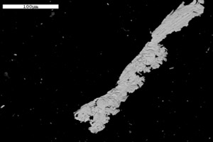
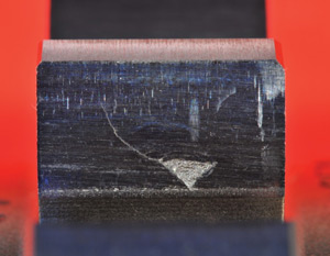
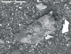
An iron shaving with scratch marks (top) and soil (above) were found in the oil sample.

Case Study #3: Wrist Pin Bearing Failure on a Diesel Locomotive

Prior to a wrist pin bearing failure, oil samples from a diesel locomotive were sent to two different laboratories for routine oil analysis. The first laboratory issued wear alerts on possible wrist pin bearing wear four weeks prior to the failure, while the second laboratory indicated no abnormal wear was taking place. A resample was taken, and again the second lab did not find any abnormal wear, while the first lab issued another wear alert.
The fleet owner decided to stop the locomotive to find out whether the alerts issued by the first laboratory were justified. It was discovered that the wrist pin bearing had failed with damage to four power packs. An investigation was launched to determine the root cause that resulted in the different diagnoses from the two laboratories.
Routine oil monitoring tests were performed, including spectrometric analysis using RDE spectrometry and PQ. An EDX analysis using the SEM on the filter debris was conducted after the sample was filtered through a 0.8-micron-filter membrane and rinsed with pentane to remove oil residue. The results of the RDE spectrometric analysis revealed an increase in silver, copper and iron, while the SEM analysis confirmed the presence of particles larger than 10 microns.
Since both laboratories performed similar analysis on a routine basis, the investigation focused on the differences in the techniques used by the two labs. The only major difference found was that the laboratories employed different spectrometric techniques to determine the wear metal content of the samples, namely ICP and RDE spectrometry.


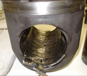
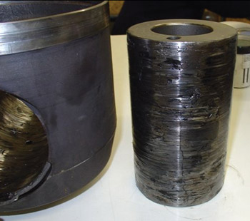
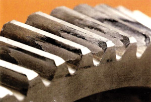
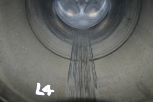
These images of a locomotive engine
reveal wrist pin bearing failure.

The primary variation between the two techniques is the way the sample is introduced to the system. For ICP analysis, the sample is diluted prior to introduction to the instrument. Therefore, it’s possible that the particles settled prior to analysis. The ICP also uses a peristaltic pump and transport system, which is subject to blockages.
In addition, the size limitation of the ICP is 1 to 3 microns, while the range of the RDE is 8 to 10 microns. The SEM analysis confirmed the presence of particles larger than 5 microns, so it seems the failure progressed beyond the point where the ICP could detect the wear particles but remained within the range of the RDE.

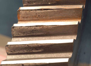
Case Study #4: Scored Liner and Piston Wear on a Diesel Locomotive

As part of an oil analysis program, the crankcase oil of a locomotive was monitored on a monthly basis. However, no samples were received for the period between January and the end of June. The engine failed at the end of September.
The reason for concern was that all laboratory reports returned with no indication of an increase in wear metal content. An investigation was initiated to explain why the laboratory tests failed to detect any increase in wear when it was evident that abnormal wear was taking place from the mechanical failure that occurred.
Since no abnormalities were found except for fuel dilution over a prolonged period, the investigation focused on sampling intervals and techniques that could have affected the results.
Routine oil monitoring tests, including spectrometric analysis using RDE spectrometry, were performed, as well as EDX analysis using the SEM on the filter debris after the sample was filtered through a 0.8-micron-filter membrane and rinsed with pentane to remove oil residue.
The results showed severe fuel dilution. The RDE spectrometry indicated no increase in metal content since the previous sample was analyzed. The EDX analysis revealed that isolated large particles (larger than 20 microns) of heavy metals and other inorganic oxides were present on the filter. Many of the larger particles were iron or iron oxides. The small particles consisted mainly of calcium sulphate.
 

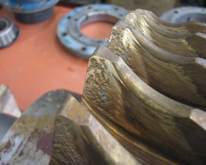
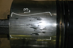
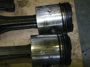
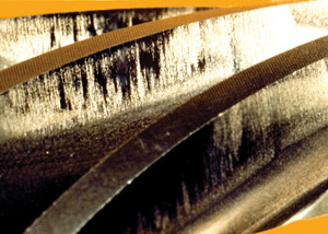
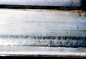
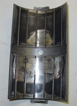
These photos of a locomotive engine indicate a severely scored liner and piston wear.

Lowering of the fluid’s viscosity, which may have resulted from fuel dilution in the engine, aggravated the tendency of particles to settle. Therefore, it is possible that suspended particles had settled to the bottom of the sump and were not included in the sample.
In the earlier stages of failure, smaller particles were produced (likely during the period when no samples were submitted). As the failure progressed, the size of the particles increased. Since particles larger than 10 microns were found, it is possible that the failure progressed beyond the point where the RDE could detect the wear particles. Thus, severe fuel dilution over a prolonged period of time combined with not submitting oil samples at the initial stages of failure resulted in the inability to detect the failure through a routine oil analysis program.

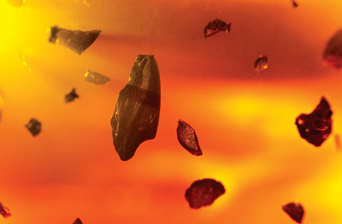
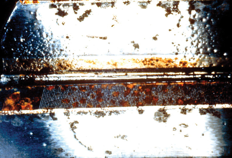
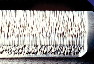
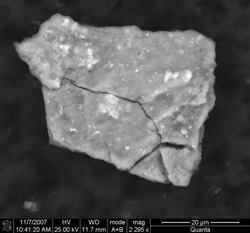
A particle larger than 20 microns
was found in the oil sample.

In conclusion, it is apparent that removal of particles from a system prior to sampling by means of indiscriminate filtration, improper sample handling and settling of particles can result in the loss of important evidence that could lead to the early detection of possible failures or assist in root-cause analysis.
Remember, the purpose of oil analysis is to avoid failure before it happens. Sensitivity with regards to particle sizes and size limitations of analytical techniques relative to sampling intervals is vital to reach this ultimate goal. In the end, the success of an oil analysis program to detect possible failure modes relies on the ability of the mechanical engineer, tribologist, sampler, analyst and diagnostician to treat and react to the presence of particles in the appropriate manner.

Wednesday 3 April 2013

ISO Oil Cleanliness vs Operating Pressure

An informative article I read on Reliable Plant Newsletter this morning.
http://www.machinerylubrication.com/Read/28977/consider-contamination-control

Consider Contamination Control Before Buying Hydraulic Equipment


These days, best-practice contamination control is more like an accepted pre-condition for reliability. Given contemporary advances in technology for excluding and removing contaminants, it could be said that failure to control contamination is a failure of machine design rather than a failure of maintenance.
That said, effective contamination control is not something to be taken for granted. The results you get are only as good as those you demand, which is why it never hurts to be reminded of the reliability benefits of kicking fluid cleanliness up a notch. Consider the following case study:
A sugar mill was operating a fleet of more than 20 sugar cane harvesters. The typical fluid cleanliness of the hydrostatic transmission for the ground drive on these machines was ISO 22/20, and they were suffering regular pump failures - three pumps per machine, per season, on average.
The sugar mill contracted a local hydraulic engineering firm to investigate the recurring pump failures. They recommended a specification change to the ground-drive hydraulic motors and an upgrade of the filtration.
One machine was modified as a prototype, and after showing promising results, two more machines were modified in the first season. The ISO cleanliness code on the three modified machines was 18/15 or better.

71%of machinerylubrication.com visitors consider contamination control targets before purchasing new equipment

By the fourth year, 15 machines had been modified. The mill was now changing out one variable piston pump per machine every three seasons - a nine-fold increase in pump life.
Armed with this data, the sugar mill convinced the cane-harvester manufacturer to incorporate the same transmission and hydraulic filtration design at the factory.
This is not a scientific study into the benefits of improving fluid cleanliness alone, because clearly, other changes were made to the hydraulic circuit in addition to upgrading the filtration. We’re also not told what influence (if any) these modifications had on other important operating parameters such as pressure and temperature.

Example of Hydraulic Fluid Cleanliness Targets


But what can’t be disputed is the drastic improvement in pump life. As a result, the equipment end user demanded that the machine manufacturer improve the specification (and initial cost) of the equipment they were purchasing. Of course, this was after the economic benefits of doing so had been clearly demonstrated to the end user.
For this hydraulic equipment owner, it was a case of “I once was blind, but now I see.” Prior to this education, they likely would have looked at two cane harvesters of similar capacity from competing manufacturers and bought the cheapest one - with little or no regard to machine reliability or life-of-machine operating costs.

Factors in Setting Target Cleanliness Levels

There are two important factors for hydraulic systems that can help you set target cleanliness levels. One is how sensitive the components are to contaminants. This is called contaminant tolerance.
The second factor is pressure. There is a disproportionate relationship between pressure and contaminant sensitivity. Basically, the greater the pressure, the far greater the contaminant sensitivity the components have to contamination.
After you have considered the component type and the pressure, also consider the duty-cycle severity, the machine criticality, the fluid type and safety concerns. All of these factors collectively can be used to set target cleanliness levels in hydraulic systems.

Even though they got it the wrong way around, this machine owner got it in the end. If you’re a hydraulic equipment buyer/owner, the key takeaway of all of this is that the best time to consider these issues is before you purchase a piece of equipment.
By starting with the end in mind, you get the maintenance and reliability outcomes you desire - before the machine even gets delivered. Like in the cane harvester example, you specify the contamination control targets you want to achieve based on your reliability objectives for the piece of equipment and instruct the manufacturer to deliver the machine appropriately equipped to achieve these targets.
Based on the weight and viscosity index of the hydraulic oil you plan to use, you determine the minimum viscosity and therefore the maximum temperature at which you want the machine to run. You then instruct the manufacturer to deliver the machine equipped with the necessary cooling capacity based on the typical ambient temperatures at your location, rather than accepting hydraulic system operating temperatures dictated by the machine’s one-size-fits-all designed cooling capacity - as is the norm.
For example, say you are about to purchase a 25-ton hydraulic excavator that is fitted with brand “X” hydraulic pumps and motors. According to the pump manufacturer, optimum performance and service life will be achieved by maintaining oil viscosity in the range of 25 to 36 centistokes. You also know that in your particular location that you expect to use an ISO VG 68 weight hydraulic oil, and the brand of oil you are already buying has a viscosity index of 100.
This being the case, the pump manufacturer tells you, based on the viscosity and viscosity index of the oil you plan to use, that if your new excavator runs hotter than 70 degrees C, the performance and service life of the pumps and motors will be less than optimum. Not only that, with 70 degrees C as the maximum operating temperature, the oil, seals, hoses and almost every lubricated component in the hydraulic system will last longer.
So being the sophisticated hydraulic equipment user that you are, you say to the manufacturer before you order the machine: “I expect ambient temperatures at my location as high as 45 degrees C, and under normal conditions (i.e., no abnormal heat load in the system), I require this machine to run no hotter than 70 degrees C. If you deliver it to the site and it runs hotter than 70 degrees on a 45-degree day, then I’ll expect you to correct the problem - at your cost.”
You could continue by specifying other requirements that have an impact on hydraulic component reliability, such as that all hydraulic pumps have a flooded inlet, that no depth filters or screens be installed on pump intake lines and that no depth filters be installed on piston pump and motor case drain lines.
At the very least, as the cane harvester story demonstrates, the next time you or the company you work for are purchasing hydraulic equipment, be sure to define your fluid cleanliness and operating temperature/viscosity targets in advance and make them an integral part of your equipment selection process.

About the Author
Brendan Casey
Brendan Casey has more than 20 years experience in the maintenance, repair and overhaul of mobile and industrial hydraulic equipment. For more information on reducing the operating cost and ... Read More

Friday 8 March 2013

Analyzing Gear Failure

Article from Reliable Plant Newsletter
http://www.machinerylubrication.com/Read/28978/analyzing-gear-failures


Best Practices for Analyzing Gear Failures


With all the different gearbox failure modes, it’s important to be aware of the various tests that can be used to develop and confirm a hypothesis for the probable cause of failure. Lubricant samples can provide immediate means to detect contamination or other adverse changes to the lubricant. These samples can be sent to a laboratory for further analyses. There are also a number of tests that can be performed on-site and at a low cost to check for lubricant contamination or oxidation.

Appearance Test

The simplest test is visual appearance. Often this test will disclose problems such as gross contamination or oxidation. Look at the lubricant in a clean, clear bottle. A tall, narrow vessel is best. Compare the sample to a sample of new, unused lubricant. The oil should look clear and bright. If the sample looks hazy or cloudy, or has a milky appearance, there might be water present. The color should be similar to the new oil sample. A darkened color might indicate oxidation or contamination with fine wear particles. Tilt the bottle and observe whether the used oil appears more or less viscous than the new oil. A change in viscosity might indicate oxidation or contamination. Look for sediment at the bottom of the bottle. If any is present, run a sedimentation test.

Sedimentation Test

If any sediment is visible during the appearance test, a simple test for contamination can be performed on-site. Place a sample of oil in a clean, white cup made from a non-porous material that is compatible with the lubricant. Cover and allow it to stand for two days. Carefully pour off all but a few milliliters of oil. If any particles are visible at the bottom of the cup, contaminants are present. Resolution of the unaided eye is about 40 microns. If the particles respond to a magnet under the cup, iron or magnetite wear fragments are present. If they don’t respond to the magnet and feel gritty between the fingers, they are probably sand. If another liquid phase is visible or the oil appears milky, water is likely present.

This image shows how severe misalignment
can limit the contact area and cause macropitting.

Odor Test

Carefully sniff the oil sample. Compare the smell of the used oil sample with that of new oil. The used sample should smell the same as new oil. Oils that have oxidized have a “burnt” odor or smell acrid, sour or pungent.

Crackle Test

If the presence of water is suspected in an oil sample, a simple on-site test can be performed. Place a small drop of oil onto a hot plate at 135 degrees C. If the sample bubbles, water is above 0.05 percent. If the sample bubbles and crackles, water is above 0.1 percent. When carrying out the crackle test, the inspector’s health and safety must be taken into consideration by wearing eye protection, for example.

Why Take Oil Samples from a Failed Gearbox?

Laboratory analysis of oil samples from a failed gearbox might answer the following questions:
  • Does the oil meet the original equipment manufacturer (OEM) specification?
  • Was the oil contaminated?
  • Was the oil degraded?
  • Does the oil contain evidence useful for finding the root cause of failure?
  • Is the oil representative of the service oil?
45%of lubrication professionals consider the appearance test to be the most effective on-site test to check for lubricant contamination or oxidation, according to a recent survey at machinerylubrication.com

Does the Oil Meet the OEM’s Specification?

Sometimes a gearbox fails because the wrong oil was used. To prove whether the oil meets the OEM’s specification, the following laboratory tests should be performed on used oil samples and compared to laboratory test results from samples of fresh, unused oil that conforms to the OEM’s specification:
  • Viscosity at 40 degrees C and 100 degrees C (ASTM D445)
  • Spectrometric analysis to determine elements in the oil (ASTM D5185 or D6595)
  • Acid number (ASTM D664 or D974)
  • Infrared spectroscopy to determine additive content (ASTM D7412, etc.)

Micropitting often will have a pattern that indicates misalignment.


A lubricant with inadequate anti-scuff additives caused scuffing on this spiral bevel pinion.

Was the Oil Contaminated?

The fatigue life of gears and bearings is adversely affected by water. For example, as little as 50 ppm of water reduces rolling bearing fatigue life by 75 percent. Therefore, the Karl Fischer titration method (ASTM D6304) should be used to determine the water content. Other laboratory tests such as viscosity, spectrometric analysis and infrared analysis can help determine if other fluids such as the wrong oil, flushing oil or coolant contaminated the service oil. Spectrometric analysis might disclose contamination via environmental dust by showing high concentrations of silicon and aluminum.

A lubricant contaminated with water produced corrosion on this helical gear.

Was the Oil Degraded?

The oil might lose its ability to lubricate if its viscosity changes significantly or if it is oxidized. The manufacturing tolerance on viscosity is plus or minus 10 percent. Therefore, ISO VG 320 oil should have a viscosity that falls within the range of 288 to 352 centistokes at 40 degrees C.
There are many possible causes for an increase or decrease in viscosity. For example, some oils have additives known as viscosity-index (VI) improvers that might not be shear stable. With time in service, these oils lose viscosity because the VI improvers shear down.
In addition, overheating might cause oxidation. Contamination by water and wear debris accelerates oxidation. The following symptoms are indicative of oxidation:
  • A foul odor (sour, pungent or acrid smell)
  • A dark color
  • An increase in viscosity
  • An increase in the acid number
  • A shift in the infrared spectrum

Does the Oil Contain Evidence for Finding the Root Cause of Failure?

Wear debris in the oil may help indicate failure modes that occurred in the gearbox and reveal contaminants that contributed to the failure. Spectrometric analysis can uncover contamination via environmental dust by showing high concentrations of silicon and aluminum. These results might explain abrasion on gear teeth and bearing surfaces. Depletion of anti-scuff additives may confirm a scuffing failure, and excessive water concentration might explain corrosion.
Other test methods used to monitor abnormal wear of gearboxes include ferrous density, particle counting (ASTM D7647) and analytical ferrography (ASTM D7690).
Direct reading (DR) ferrography is a ferrous density test that measures the amount of ferrous wear debris in an oil sample. The results of DR ferrography are generally given in terms of DL for particles greater than 5 microns and DS for particles less than 5 microns in size.
Analytical ferrography allows wear particles to be observed by the analyst via microscopic analysis. In this evaluation, active machine wear as well as multiple different modes of wear can be determined. This method has an outstanding sensitivity for larger particles.
Particle counting in industrial gearboxes tells the same story as particle counting in a hydraulic system or pump application - that of cleanliness. When establishing an oil analysis program that is proactive in controlling contamination, particle counting is a vital component to the routine test slate.

This is an example of point-surface-origin
(PSO) macropitting caused by tip-to-root interference.

In this example, abrasion and scuffing
have been caused by tip-to-root interference.

Is the Oil Representative of the Service Oil?

If the oil appears very clean, it might have been changed after the failure occurred. Therefore, check maintenance records and interview maintenance personnel to determine whether the oil is representative of the oil that was in service when the failure took place.

Sampling Procedures during an Oil Drain

Always use clean, lubricant-compatible plastic or glass sample bottles and caps, and keep all sampling equipment thoroughly clean. Prior to sampling, fill out the label and attach it to the sample bottle. Be sure to record the sample point and the date.
The equipment needed for proper draining and sampling includes:
  • Clean containers for holding the drain oil
  • A wire-mesh screen
  • Four or more clean laboratory bottles (clear plastic) for taking samples
  • A large bottle for capturing excess water

First Oil Sample

Drain the oil through the screen to capture any large wear debris or fracture fragments that might be entrained in the drain oil. Take the first oil sample at the start of the drain. Be prepared to capture any free water that may have settled in the gearbox. If there is a large quantity of water, fill a sample bottle and then capture the remaining water in the large bottle. Once the water stops flowing, take a sample of the oil.


A lubricant contaminated by sand
resulted in abrasion on this spur pinion.

Second Oil Sample

Take the second oil sample near the middle of the drain. Estimate the oil level in the gearbox from the sight gauge or from direct measurements. This sample will be used to determine bulk oil properties that are more representative of the in-service oil properties.

Third Oil Sample

Take the third oil sample near the end of the drain. This sample might capture less dense contaminant fluids.
When all the calculations and tests are completed, form one or more hypotheses for the probable cause of failure and then determine if the evidence supports or disproves the hypotheses. While similar procedures apply to any failure analysis, the specific approach can vary depending on the nature of the failure and time constraints.
So whether you perform tests on-site or send oil samples to a laboratory for further analysis, be sure to select the appropriate test to help you correctly determine the probable cause of a failed gearbox.

About the Author

Robert Errichello is a gear consultant with GearTech. Contact him at geartech@mt.net.

Thursday 7 March 2013

ISO Oil Analysis Code Interpretation

An article from Reliable Plant Newsletter.
http://www.machinerylubrication.com/Read/28979/iso-cleanliness-code

How Important is the ISO Cleanliness Code in Oil Analysis?


The International Organization for Standardization (ISO) has developed a cleanliness code that is the primary piece of data reviewed on most industrial oil analysis reports. The value of this code can help determine the overall cleanliness of the monitored system. Often times, an end user will establish a target value to achieve, thus offering a level of confidence so long as the used oil sample meets this established target.
The trend in the oil analysis world is to give too much credit to the value of the ISO cleanliness code. Some laboratories have even begun to only report the ISO code. There is also a heavy reliance on this value by end-user analysts.
The ISO code is a fantastic tool to use for setting target alarms and establishing a goal to achieve and maintain as it relates to system cleanliness. It is also the perfect value to use for key performance indicator (KPI) tracking, charting and posting. However, the ISO code should play only a secondary role when it comes to evaluating used oil sample data.
73%of machinerylubrication.com visitors have used the ISO cleanliness code to set target alarms for system cleanliness levels

How the ISO Cleanliness Code is Determined

Most oil analysis samples that receive particle counting are getting what is known as automatic particle counting (APC). The current calibration standard for APC is ISO 11171. When sending a sample through an APC, particles are counted either through laser or pore blockage methods. Although different laboratories may report different particle count micron levels, an example of the various reported micron levels includes those greater than 4, 6, 10, 14, 21, 38, 70 and 100 microns.
ISO 4406:99 is the reporting standard for fluid cleanliness. According to this standard, a code number is assigned to particle count values derived at three different micron levels: greater than 4 microns, greater than 6 microns and greater than 14 microns. The ISO code is assigned based upon Table 1. This can be seen in the example on the left.
However, without seeing the raw data, the only thing the ISO code can positively identify is whether a sample has achieved the desired target value. The ISO code does nothing to help determine any type of real trend information unless the value of the raw data at the given micron levels changes enough to raise or lower the ISO code.

What the ISO Code Can Tell You

It’s easy to look at the ISO table and notice a pattern. At each row, the upper limit for each code is approximately double that of the lower limit for the same code. Likewise, the upper and lower limits are double that of the upper and lower limits of the next lower code. This is known as a Renard’s series table.
The unit of measure for particle count data is “particles per milliliter of sample.” The particle counters used in laboratories incorporate much more than a milliliter of sample. During the testing process, approximately 100 milliliters of sample are taken into the instrument. The numbers of particles are counted based on this value. The total number of particles is then compared to the number of times that 2 will go into that total count exponentially.

Staying Clean

Why is cleanliness so important? The answer is simple: competition. In such a globally competitive market where products can potentially be manufactured and shipped from overseas at a lower cost than can be manufactured from here at home, maintaining a precise level of reliability and uptime is necessary to keep costs at a manageable level. Contaminant-free lubricants and components will extend the lifetime of both, and in turn increase the overall reliability of the equipment.
Using the previous example (20/17/13), this means that at the greater than 4 micron level, the number of particles measured was at the most 2^20 and above 2^19. Since particle count data is reported in particles per mL of sample, the raw data must be divided by 100.
While the general rule of thumb is that for every increase in the ISO cleanliness code, the number of particles has doubled, this certainly is not the case in every situation. Because the number of allowable particles actually doubles within each code number, it is possible for the number of particles to increase by a factor of 4 and only increase a single ISO code.


This becomes a significant problem when you have a target cleanliness level of 19/17/14, your previous sample was 18/16/13, and your most current sample is 19/17/14. For all reporting purposes, you have achieved and maintained the target cleanliness level of 19/17/14. This suggests that your component should be in a “normal” status. Given the information presented previously, it is easy to see how you could have two to four times the amount of particle ingress and only increase by a single ISO code or have no increase at all.
The ISO cleanliness code should be used as a target. It is a value that is easily tracked for KPI reporting and a value that most people can easily understand. However, using the ISO cleanliness code for true machine condition support is limited in its effectiveness. The raw data from particle count testing allows the end user to confirm data from other tests such as elemental analysis and ferrous index. The ISO cleanliness code does not allow this cross-confirmation to occur. Reviewing the raw data of the particle counter at all reported levels is absolutely vital in performing quality data analysis on oil sample data.

Reliability & Safety goes hand in hand!

Article from Reliable Plant Newsletter
http://www.reliableplant.com/Read/28844/reliability-safety-link
The Link between Reliability and Safety


Over the last year or so, the question of reducing the cost of reliability has been ever present. Many maintenance budgets have been slashed without due process or reflecting on the true cost over time. I recently attended a conference where this was a topic of conversation. Out of all the discussions that I have heard, the most effective statement was to respond to that request from a CEO or plant manager with the following question: “How much are you willing to reduce the amount spent on safety?”

Unfortunately, not everyone makes the tie that reliability and safety go hand in hand. I am reminded of a letter that Dave O’Reilly, the CEO of Chevron Corporation, sent to employees where he said, “Reliability, like safety, is a critical element of operational excellence and requires our constant attention.” I couldn’t agree more.

Reliability drives safety and vice versa. Consider that most accidents don’t occur when things are running smoothly and the equipment has a high level of reliability. Accidents occur when we fall into reactive chaos. When a packaging machine is no longer operating in a reliable state, lots of minor stops may cause an operator to reach into a running machine (bypassing the safety procedures) and remove jammed cartons or film. The moment of frustration may cause the loss of a finger, hand or worse.

Less spending on maintenance may result in more leaking piping or vessels. The operator gives up on keeping the floor clean. Now, not only are the pipes leaking, but the main process line is acting up. When the product piles up on the end of a main conveyor due to a neglected bearing, the operator makes a mad dash to clear the pileup. On the way, he or she slips and falls in the area where the leak has created a puddle on the floor. The spiral only worsens.
The challenge that we face as maintenance and reliability professionals is to connect the dots for our leadership. We have to elevate maintenance and reliability as a profession and not have it viewed as “a necessary evil.” Sure, it is one of the most controllable costs in a site. When you toss out labor as a “sunk cost” (X number of people to produce X number of widgets), the largest (and easiest target) is the maintenance budget. Most every other cost requires capital to influence (energy costs, as an example) or is fixed via contract (logistics, raw materials, etc.) or global pricing.

While it is one of the most controllable costs, maintenance and reliability can be one of the greatest drivers of productivity and reduced costs. This is done not by slashing the budgets indiscriminately, but by keeping the focus on reliability as a long-term investment strategy.
So when you are asked by the CEO or plant manager about reducing reliability costs, ask if that leader is willing to reduce the organization’s investment in safety.

Operations & Maintenance combined! - Something to ponder about...

Copied from: http://www.reliableplant.com/Read/28849/maintenance-operations-coexist
received in Reliable Plant Newsletter.

Can Maintenance and Operations Coexist?


Most of us come from traditional plant organizations with an operations group and a maintenance group with their own supervisors and specialized skilled crafts.
One of the major European postal services decided in the late 1990s to make a change in their plant maintenance organization. In my own U.S. Postal Service, there had been talk for years of combining the operations and maintenance supervision and reducing the supervisory ranks. It is easy to say, but how do you do it? Be careful of what you wish for.
They negotiated with their union to change the working condition of “supervision” (changes in hours, wages and working conditions are negotiated contractual obligations) to put the operating equipment technicians under the operations supervisors. In doing so, they split the maintenance craft workforce and established a plant facilities maintenance support function separate from the operations maintenance function.
The facilities function had responsibility for everything but the operating equipment. That included storeroom, custodial, HVAC, all the plant’s infrastructure and the computerized maintenance management system. Work order estimating was done by the facilities planners.
Operations now had control of their own machines, both production and maintenance. The thought was to make teams that could work together and decrease downtime, better identify degradation sooner, and “keep the maintenance employees involved.” In mail-processing plants, there is considerable time spent by maintenance personnel on “area assurance,” of which operations wanted to take advantage.
In a previous article, I discussed the “enabling process design” and focused on the levels of effort and training required for making a change such as this in people’s lives. Rather than tell you the level of effort, I will relate several of the results:
  • The supervisors had problems communicating with the technicians and vice versa. The supervisor could add nothing of value to assist the technician when a piece of equipment was down and also did not know how to judge technician performance.
  • Supervisors tended to drift toward the operators and avoid the technicians until something broke down. Technicians felt they were subordinated to the operators and felt unappreciated. This led to a reduction of discretionary effort and creativity as it was not recognized.
  • The area assurance was misunderstood, and supervisors were uncomfortable for appearing lax toward technicians and pushing the operators. Cooperation between the two factions was less than before the big change.
  • The technicians felt disenfranchised, not really belonging. In maintenance, they had camaraderie, mutual support, management that championed them and a home.
  • Issues arose over planned work orders between the technicians and the estimators, and between the estimators and the supervisors, with the supervisors trying to understand the now fragmented process for which they used to be a benefactor, but for which now had a part in completing the work order.
This was implemented one plant at a time, and it became evident that maybe a plant-by-plant evaluation should determine the readiness to attempt this change. It resulted in a decision that “one size does not fit all,” and that there could be two approaches: Leave some plants as they are and implement the new structure through a modified process to address the learning from the earlier-on plants. Some early plants reverted back. It also became evident that retrained maintenance supervisors may be more successful in managing a mixed team of operators and technicians.
The lessons are many in this story. I believe that planning for such a change must focus on the roles of each player. I am a believer in getting people to verbally walk through a typical work day as though they were in the new process. This should be done with teams of all involved. Not only should this be early on to beta test a concept, but should be carried forward for all employees involved in every installation.
If you are considering any kind of change, this story is a good beginning for facilitated training sessions on enabling change, along with all of the other process management redesign tools that quality and re-engineering bring to the table.

Monday 4 February 2013

Duty Standby Regime

In the world of process plant, redundant system is being installed. Equipment such as PLC or Control System runs on a full time online fall back redundancy system. Whereas most mechanical equipment runs on a variety of duty-standby arrangement.

In my view, the most effective duty-standby arrangement has to be judged by the engineer. The question to ask is, what is the dominant failure mode. If it is a random failure mode that is dominating, there is very low risk of increase of failure for switching them every fixed period of time. If the dominant failure mode is in the realm of wear, then one might want to consider off-setting the operational hours so they don't have a perfect storm resulting in plant downtime. If the dominant failure mode is false brinelling, one might want to consider running all the redundant equipment at partial load instead!

Wednesday 16 January 2013

Managing the depth of RCM

RCM stands for Reliability Centred Maintenance. It is a process whereby a series of questions are structurally raised to conclude a maintenance requirement. It can be as tedious as a full blown RCM where you are moving on average about 3-4 Failure Modes an hour in a RCM workshop to a quick straight forward 30-50 Failure Modes an hour in a peer review workshop.

How deep to go for the RCM analysis? There're a few things to consider when making this call.

  1. How skilled are your maintenance team in addressing the Failure Modes? There is no point going into too detail if your trades does not share the understanding and knowledge. For example, carrying out vibration analysis on an equipment without a skilled person is useless. No one will be able to interpret the data and put it to good use. Your strategy would then have to be fine tuned to fixed-time replacement on an optimized shutdown interval.
  2. How critical is the equipment? The more critical it is, the more time should be invested towards making it performing reliably.
  3. What is the current state of the maintenance strategy? Is it running reliably? If it is, are we seeing potential Failure Modes that we are not addressing? A peer review to close the gap in the strategy is sufficient in this case. If the equipment is not reliable to start with, it may require a full blown RCM from scratch.
  4. There will be times where you run into a highly critical equipment but yet the Failure Modes are highly unlikely. The facilitator or reliability engineer would have to make the call whether a full blown RCM is worthwhile or manage the risk with a peer review process to ensure all gaps in strategies are covered. This require local plant experience that none of your external consultants have. Re-emphasize, invest in your reliability team!
  5. ???


A note to reliability managers out there, if a person pitch you they can deliver RCM workshop at 15 Failure Modes an hour, be very wary about it. You get what you pay for. Quality takes time and it is inevitable in RCM! Again, your best value is through having invest in a very good reliability engineer on your side. After all, the RCM databases will still require maintenance and update in-house, unless you are ready to pay the continual work from the consultancy.

Post-Operational Readiness Project (Continuous Improvement)

With the growing world, the mega projects keep coming. With mega projects comes the need for certainty to the investor. In the world of plant maintenance, the certainty comes from Operational Readiness Project. To some, it is a common phase of a project, to some parts of the world, it is an alien that they have never heard before, that includes experienced multinational EPCM contractors.

If you are deciding on the OPEX of a project, and your EPC or EPCM contractor gives you a cost projection that says, oh, it's 3-5% of capital cost. Ask them where that figure comes from, chances are they'll say it's an estimates from historical data. I can also tell you the figure is INCORRECT. Why? It is because your operating cost depends on the quality of your equipment too! Not in linear, or able to be defined by any mathematical algorithm model! It has to be painstakingly compiled, equipment by equipment, building up to the complete plant! A simplified example, a Japanese car OPEX will be very different from a German car OPEX. They have different service intervals, differing coping ability in operating bandwidth & context, difference in material cost, different in complexity. In some cases, higher capital upfront is justifiable! This has to be evaluated on a case by case basis in details.

Planning and budgeting an Operational Readiness to get your master data up to standard, and having all your equipment registered is essential to every process plant. Once up and running, the OEM recommended maintenance plan has to be put in. No, the process does not end here. You need your reliability team to continually manage the plant changes, and it has to update the master data to reflect the changes occur over-time. As the equipment fails in service, reliability engineers need to assess and evaluate your maintenance task to optimize the time and cost for improvement in reliability, increase in production and reduction in cost. This is an on-going task that cannot be neglected.

From experience, a neglected Master Data can cost upwards of $10 million dollars or more to clean up in a brownfield project and a trailing $1 million dollars a year of labour to keep it clean as they go. If a dedicated person acting as the gate-keeper since day 1 at a price of $150,000 a year, imagine how much less money needs to be re-invested to maintain the original business case projected reliability figures!

A lesson for the Executives out there, Operational Readiness does not guarantee you the reliability outcome. Reliability is a culture and an on-going continuous process. Invest in your reliability team!

Reliability Modelling

I have been working full on until New Year building component library for a consultancy and running reliability modelling. I have run into a lot of issues with the model and would like to share them to promote an understanding.

The very first thing you do as an engineer is always question the validity of those data you acquire. In summary, I would not recommend doing reliability modelling. My personal opinion is, it is a waste of time, effort and money. If you are looking at doing reliability modelling, chances are, your existing plant reliability is not great and your reliability knowledge is not comprehensive. For the accuracy you get, you are better off with a 0.9 factor of industry average reliability figure. No modelling out there I have seen is accurate enough for any good use. If you are doubtful on the quality of people you are able to hire into the maintenance team, use a factor of 0.7 and you should have a somewhat conservative availability figure. Yes it looks ugly, yes it looks unrealistically low, but I'm sorry to say, that is reality of the availability and reliability figure you should expect for saving cost hiring cheap people. I could not emphasize enough, good asset management and reliability starts with good people.

Back onto the topic I was suppose to be writing about - Limitations of reliability model. Firstly, ALL reliability model I have seen is designed in series. It is all well and good if your process is in series like a simple production line of a simple mine site, if you have a complicated processing plant, your reliability model will not do. In fact, there's so much work trying to design the model to fit your plant, it is just not worth the effort. Unless there's a free template already setup similar to your plant and takes just a little bit of effort to patch up, there's no point going down this path.

Secondly, in a complex process plant, you will have varying equipment MTBF and MTTR. Every plant's figure is unique. For the model to be accurate enough to be of any use, it has to be from your plant, your production forecast, you historical availability, and reliability. This is because as the errors build up in the reliability model, the final result is again of not much use to you as the owner.

Thirdly, a complex equipment in a complex plant will have a long list of failure modes to prevent. Some of these failure modes will be attended to in one work task and reset their likelihood of occurrence and budgeted life. None of the reliability model I seen cater for this.

With this three fundamental issues in modelling unresolved, I would not recommend any company looking at carrying out the modelling without understanding the limitations of it.