Saturday 23 July 2016

A Practical Approach for Evaluating Oil Analysis Results with Limit Values

Article extract from Machinery Lubrication newsletter:
http://www.machinerylubrication.com/Read/29829/a-practical-approach-for-evaluating-oil-analysis-results-with-limit-values

The evaluation of oil or grease analysis results is often a tough job for a diagnostician, demanding experience in mechanical engineering and chemistry. However, modern tools and statistical methodologies can support and improve the process. The first step is to define a proper set of test methods that delivers sufficient parameters for answering important questions about the sample while still being as economical as possible.

After determining the test parameters, the next challenge is to set up limit values and guidelines for the evaluation. In some cases, general limit values are available. However, in many cases, oil, component or equipment manufacturers cannot or will not supply complete limit sets. So how can a meaningful diagnosis be created? One way is with the help of an experienced engineer who knows the application and when critical values are exceeded. It is also easier if previous samples exist. Developing parameters over a period of time can identify layers or single parameters that move away from the regular trend line. Absolute limit values must also be applied in order to have a fixed reference point for the critical region.

An adequate set of oil analysis results from the same or comparable equipment/application is the baseline for statistical methods. ASTM D-7720 describes an approach for identifying alarm limits by statistical methods, but a large set of data and statistical guidelines do not automatically provide proper limit values. The quality of the data set can have a significant impact on the statistical results. It may make the difference between having reasonable statistically based limits or nonsense.

This article will show how carefully filtered data sets within a sophisticated structure can deliver valuable limit values. The system, which is based on an application matrix, enables oil samples to be categorized with as much detail as the sample information allows. Combined with an advanced evaluation program, this is the basis for defining limit values, applying them with evaluation guidelines and proving them on a regular basis.

Analyzing an Oil Sample

The analysis of a used oil sample produces a lot of data. A typical lab report contains in the range of 20 to 40 single measurement results. In order to provide a proper diagnosis or trigger the necessary actions based on the analysis, typical or normal ranges for each element must be known. The oil type, construction, maintenance and operating conditions are the four main influencing factors for evaluating an oil sample.

A single rating for each oil analysis parameter does not cover the complexity and interdisciplinary knowledge in the fields of mechanical engineering, chemistry, tribology and lubrication that must be applied. If an evaluation is based on one element that has exceeded a limit, incorrect interpretations are possible. Some labs offer a comment for every oil sample, pointing out critical areas of the analysis along with recommendations for the next maintenance action. However, lab reports generally do not contain limit information in order to avoid misinterpretation by the end user.

Limit Values

Most oil analysis reports from commercial laboratories contain a rating based on the traffic-light principle. This utilizes a three-stage color code (green, yellow and red) to quickly indicate the severity of a sample result. If a large number of samples must be handled, it may make sense to filter the yellow- and red-flagged samples in order to decide what kind of maintenance action is necessary. Green-flagged samples can be stored for trending and documentation.


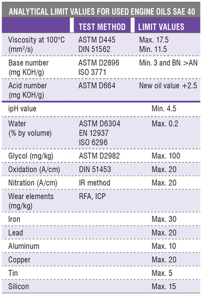
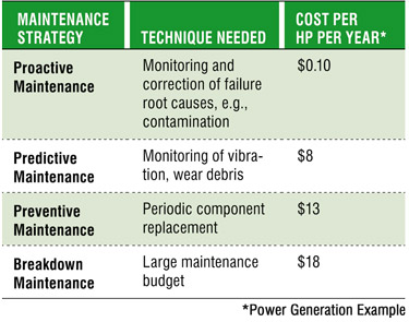
Figure 1. An example of an official limit table

The coding system should not be too complicated. Otherwise, it loses its advantage of providing quick and simple decision guidance. At the same time, it must be reasonable and consistent for comparable oil analysis patterns. Proper limit parameter sets that can be both absolute or trend-based are the basis of this consistency.

Standardized processes for the creation and revision of limit values combined with well-founded guidelines for the recognition of failure modes and the identification of normal conditions are fundamental for a high-quality oil analysis program. The opposite of such a methodology is an empirical approach based on the knowledge of an experienced diagnostician. This expert knowledge is very valuable and should be used to prove whether limits are reasonable. However, empirical knowledge is not the right methodology for managing a standardized oil analysis program with a proactive maintenance approach.

A Different Perspective

Looking for existing limit sets for specific applications can reveal different results. While limit information may not always be available, there are industrial fields where detailed guidelines exist. Among the groups that set limit values include component manufacturers, original equipment manufacturers (OEMs), oil companies, laboratories, and technical groups and associations.

Component manufacturers often define limits for single parameters that have a direct impact on the component’s lifetime or performance. Examples would include manufacturers of hydraulic components offering recommendations for oil cleanliness or a roller bearing manufacturer stating that a bearing reaches the calculated fatigue lifetime only if the contamination level is within a certain range. This information is valuable, but it is often too general and limited to certain aspects of an oil sample. Nevertheless, component limits are a good reference point if OEM limits are not provided.


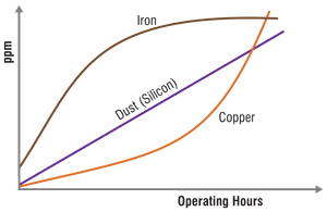
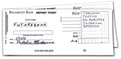
Figure 2. The function of trend over time

If OEM limits are available, they should be considered, especially if they are related to warranty issues. For some types of equipment, detailed OEM limits exist, including information about wear values, oil condition and contamination. Their main purpose is to clearly define the conditions for safe equipment operation.


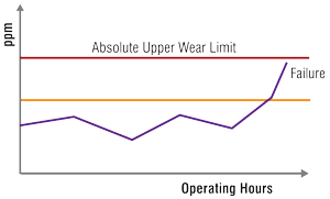
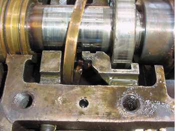
Figure 3. Absolute vs. trend limits

Limit values and evaluation guidelines can also be standardized. Standards may be independent and official, such as those from ASTM, or based on the work of other specialized associations or organizations. Often these limits are available for equipment with strict safety and reliability requirements. In these cases, the limit values should be considered very closely.

Limit values from oil companies are generally focused on oil condition. The main intention is to provide guidelines for detecting when the oil is no longer fit for further use.

Some laboratories use sophisticated computer software to support the creation and administration of equipment- and oil-type-related limit sets based on statistical and trend-based methodologies. Actual samples are connected using a matrix code with corresponding limit sets. This allows a computerized flagging of every parameter. The automated system can increase the speed and quality of the evaluation.

Absolute vs. Trend Limits

The limit information described previously is mainly absolute and does not reflect historic trend development. However, sometimes limit values relating to operating hours or distances are available, especially from engine manufacturers. This means the permissible change of a parameter over time is defined, such as iron per 100 hours of operation. Still, in most cases, absolute limits are valid for a typical overhaul or oil drain interval. If no limit is exceeded, no maintenance actions are necessary and the interval may be extended.
The evaluation of analysis results based on absolute limits has numerous benefits. For instance, it provides simple handling, quick orientation and can be statistically proven. However, there are also limitations, such as often being valid only for defined intervals. Nevertheless, absolute limits can be effective in some cases. Generally, this is when the failure modes and root causes are known, or the oil property requirements are closely defined and a change in these properties can be directly connected to problems during operation.


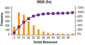
Figure 4. An example of the iron distribution
for a wind turbine gearbox
The surrounding conditions and the goal of the oil analysis are also important. If the samples are always taken during the oil change and the aim of the analysis is to identify repair actions or upcoming problems, statistically based absolute limit values will be sufficient for the evaluation.


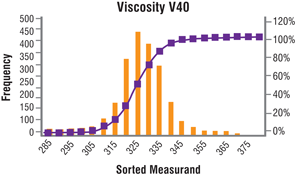
Figure 5. An example of the viscosity
distribution for a wind turbine gearbox
The longer the oil drain intervals and the higher the priority of a proactive approach for an oil change, the more important trend limits become. This is especially true for oil analysis parameters that are a function of time.


Trend limits offer several advantages, including a more detailed evaluation, greater consideration of historic data and actual operating conditions, and an early warning of upcoming problems.


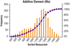
Figure 6. An example of the additive
distribution for a wind turbine gearbox
Of course, trend evaluation is only effective if enough previous samples are available. The sampling procedure and location can also have a significant effect on the final results. For trend evaluation, a sample must always be taken from the same location using the same procedure. If the operating or maintenance conditions change, they also can impact the trend line and must be considered. For most samples from the field, a combination of both methods seems to be the best approach.


Defining Properly Set Test Methods

Oil analysis can be compared to a puzzle with every piece related to a single test. If only single pieces are available, the complete picture will not be captured.
Oil-aging factors, oil properties, contaminants or wear information depend on the application from which the oil sample is taken. Properly set test methods with sufficient parameters are important to be able to provide the right answers. At the same time, the test set should be as economical as possible in order to support trend-based analysis.

Statistical Methodologies

For the statistical evaluation of limit values based on historical data, two basic methods can be applied: statistical process control (SPC) or a cumulative approach.

SPC Method

SPC is a statistical methodology for the optimization of production and service processes. The SPC theory was developed by Walter A. Shewhart in the early 1920s. Shewhart defined two mechanisms based on the idea that the quality of a product depends on the variation of every part from which the product is made. The first mechanism is a common source variation from the average that is controlled and natural for the process. The second mechanism is a special source variation that is unnatural and can be caused by machine or material failures. These two mechanisms must be clearly identified for a set of parameters that describe the process quality. If the parameter set is normally distributed and the diagram is bell-shaped, the standard deviation can be applied for the definition of limitations.

According to these limits, a decision is possible on whether the variation is normal for the process (common source) or outside the control levels (special source). For production processes, these considerations have led to the introduction of quality cards containing upper and lower control limits. Today, the SPC methodology can be used to control any type of process. In the case of alarm limits based on historical sample data, the standard deviation is also a valuable tool.

Cumulative Method

If the distribution of the measured values does not fit the normal distribution, the standard deviation cannot be applied. This is the case when the mean and median are different or the distribution is skewed or bimodal.

A zero-reference skewed frequency distribution is common for applications where the oil is not changed according to defined intervals and parameters increase over time. Typical parameters include wear, oxidation, acid number, color and contaminants. A high-reference skewed frequency distribution is normal for applications without static oil changes but with parameters that start with an initial value and decrease over time. Standard parameters would include additives, base number and viscosity.

Besides the parameter, the application also has an impact on the distribution of the data. This means that the distribution for every parameter or measured value from a data set must be evaluated in detail and that the same parameter can fit into different distribution schemes for various applications.

Practical Examples

The following examples demonstrate how statistically based limits become more precise if the population is broken down to specific machine types. In the second example, the statistical analysis revealed failure modes by drawing attention to the samples with special cause variation.

Limit Values from Wind Turbine Gearboxes

The wind industry has experienced tremendous progress during the last 20 years. The power output of modern wind turbines has increased 50 to 100 times in comparison to the first models of the 1990s. As a result, gearboxes have become much larger. This progress has also had an impact on lubricant requirements and maintenance practices. The trend for modern turbines has been toward high-performance synthetic lubricants. Although the price of these products is higher, their aging stability is significantly increased, which provides an opportunity to reduce the overall maintenance costs by extending oil drain intervals based on oil analysis results. Of course, this means the limit values must be modified.

Figures 4, 5 and 6 show the distribution of iron as a wear element, molybdenum as part of the additive system and viscosity as an important parameter for fluid film formation. The distribution of iron is typical for an application where no fixed oil drain intervals are defined. The iron content initially is low but increases over time due to normal wear processes. For this zero-reference skewed frequency distribution, a cumulative method should be applied to define the limit values. The iron range for this population is quite small, which indicates that no significant amount of sample with special cause variation is included. The statistical approach should deliver reasonable limit values.

The viscosity distribution is bell-shaped. The median and mean are in the same range. SPC and the standard deviation can be used to identify alarm values. Limit values already exist for this parameter based on the ISO viscosity grades. In this case and for this special oil, the limits could be defined more precisely according to the statistical evaluation.

The evaluation of the additive molybdenum also shows a bell shape, but the distribution is slightly high-reference skewed and bimodal. The median and mean are different, which indicates that the cumulative approach should be chosen. The population should also be investigated to identify samples with special cause variation.


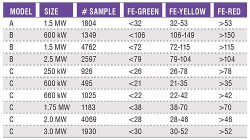
Figure 7. Iron limits for different wind turbine models

Figure 7 contains warning values for iron in different wind turbine models. It illustrates how statistical methods can be much more precise. These statistical-based limits can be combined with trend-based limits to help determine whether an increase in iron is within the acceptable range when compared to the previous sample.

Limit Values for Hydraulic Final Drives

Another example comes from hydrostatic final drives. These systems are used as crawler drives for excavators and agricultural machinery. Oil samples are often taken from these systems during the oil drain procedure with static intervals between 1,000 and 2,000 hours. The main purpose of the oil samples is to confirm that the right lubricant is in use, contamination levels are below permissible limits and wear rates are normal.


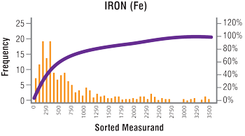
Figure 8. An example of iron distribution for a crawler drive

In general, the evaluation of oil analysis results for this application is suitable for absolute limit values. Figure 8 shows the distribution of iron for a crawler drive. Results for different models were from the same manufacturer, and for all samples, a comparable oil type was used. The main goal of the statistical evaluation was more precise wear limits.


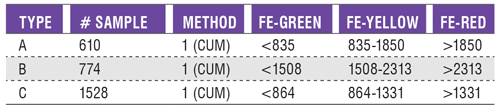
Figure 9. Limits influenced by special cause variation

Figure 9 shows the results of the cumulative method. Unfortunately, the new statistically based warning limits differed significantly from the actual limits in use based on experience. The new calculated limits seemed too high, and the unusual wide range of iron distribution supported this estimation. A closer look at the last 20 percent of the distribution revealed that the data population contained a large number of variations associated with uncommon causes. Two independent but major effects were identified: a loss of viscosity due to contamination with hydraulic oil and high silicon content, which indicated high dust levels due to damaged seals.


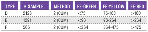
Figure 10. Typical iron limits for final drives

Figure 10 shows the statistically based limits for newer models from the same manufacturer. The wear limits are significantly lower and correspond with the previously experienced wear levels for normal conditions. The two problems of the older final drive generation have been solved for the newer generation.

In conclusion, it is important to keep in mind that oil can talk and that limit values are an essential tool for evaluating analysis results from used oils in order to rate a machine’s wear, oil condition and level of potentially harmful contaminants. While limit information can be provided by a variety of sources, in some cases it may not be available. General or global limit sets also are not usually valuable for condition monitoring. Depending on the application, absolute or trend-based limits, or a combination of both, often deliver the best results.

Thursday 21 July 2016

Which Hydraulic Issues Deserve More Attention?

Article extracted from Machinery Lubrication newsletter:
http://www.machinerylubrication.com/Read/29349/hydraulic-issues-attention

At a recent site meeting where I was investigating a series of premature hydraulic pump failures, the client opened the proceedings with a brief history on the machine, an account of the events leading up to the failures and then pushed a stack of oil analysis reports across the table.

After I finished taking notes on what I’d just been told, I inquired about the hydraulic system’s normal operating temperature range. An uncomfortable silence filled the room. Eventually, the client shrugged his shoulders. I then asked about the hydraulic system’s operating pressure range. With a blank and partly worried look, the client replied, “Err... dunno. We don’t monitor either of those things.”

90%of lubrication professionals say a lack of attention has negatively impacted the reliability of equipment at their plant, based on a recent poll at machinerylubrication.com

At the end of the meeting, we took a walk to the control room. As it turns out, both operating pressure and temperature were displayed on the default screen of the programmable logic controller (PLC). This crucial data, from a reliability perspective at least, was hidden in plain view among a lot of apparently more important and closely watched production information.
In my experience, such narrow concentration of attention within departments is not uncommon. The result is something called inattentional blindness - too busy looking at one thing to see some other thing that is equally or even more important.

It might sound trivial, but inattentional blindness can be fatal. On Dec. 29, 1972, Eastern Air Lines Flight 401 was forced to abort its initial approach for landing into Miami, Fla., because the light that indicates when the plane’s nose wheel is down and locked into position had failed to illuminate.


After flying around and pulling up to 2,000 feet, the captain and his co-pilot became so fixated on the suspect light fixture that they failed to notice that the autopilot had been disengaged. As the plane dropped through 1,750 feet, an altitude warning alarm, which was clearly audible on the black-box recording, went off in the cockpit. However, both pilots were so focused on the light fixture that neither of them consciously registered the noise.

Co-pilot: “The tests didn’t show that the lights worked anyway.”

Captain: “That’s right.”

Co-pilot: “It’s a faulty light.”

Directly in the pilots’ line of sight, the altitude meter was spiraling downward. It’s possible both pilots actually looked at it but failed to register what it was telling them. Only when the plane was 7 seconds from impact did the co-pilot finally realize that something was seriously wrong.

Co-pilot: “We did something to the altitude.”

Captain: “What?”

Co-pilot: “We’re still at 2,000, right?”

Captain: “Hey, what’s happening here?”

The captain pulled back hard on the stick, but it was too late. The plane crashed into the Florida Everglades, killing 101 people. The nose wheel did in fact lock into position during the initial approach. It was the $12 indicator light that was faulty (the bulb had burnt out).

The Importance of Visual Inspections

Many equipment inspections are visual, and checking oil levels is the most common visual monitoring activity. Numerous potential machine failures are prevented by an attentive individual who notices a low or nonexistent oil level. Other valuable functions can also be performed as part of the visual inspection. Lubricant issues such as oil contaminated with water or other materials, badly degraded or oxidized oil, and excessive foaming, as well as other machine conditions including excessive vibration, loose belts, loose drive chains and loose or missing fasteners are all examples of what should be routinely documented and scheduled procedures. This should serve as the foundation of a condition monitoring program, no matter how sophisticated.

This is a dramatic (and tragic) example of being too busy looking at other things to see something that’s really important - and one that had dire consequences. On a different level, I see this a lot in my consulting work. Clients often come to me fixated on one issue or problem, when in fact there is a more significant one staring them in the face that warrants their attention first. Usually this is not due to a lack of understanding but rather a lack of attention or, more precisely, a misallocation of attentional resources between or within departments, similar to the situation described at the beginning of this article.

One of the best assets a consultant in any field brings to the table is a fresh set of eyes. Had a third pilot walked into the cockpit of Eastern Air Lines Flight 401 as the drama was unfolding, it’s highly likely his “fresh eyes” would have immediately seen what the incumbent pilots could not.

My wider point is that none of us is immune to inattentional blindness. The first step in avoiding its pitfalls is to be conscious of it.

The crash of Eastern Air Lines Flight 401 changed the way pilots are trained. The problem with the faulty light bulb was not just that the captain fixated on it, but that the co-pilot did, too. The entire available pool of attentional resources was focused on a single thing.

To avoid this situation whenever you are operating, maintaining or troubleshooting hydraulic equipment, regularly ask yourself: What else should I be paying attention to right now?


About the Author
Brendan Casey has more than 20 years experience in the maintenance, repair and overhaul of mobile and industrial equipment. For more information on reducing the operating cost and increasing the ... 

Avoiding Common Gearbox Lubrication Problems

Article extracted from Machinery Lubrication newsletter:
http://www.machinerylubrication.com/Read/29404/gearbox-lubrication-problems

The right-angle worm gearbox is a simple device that is used widely in manufacturing facilities. Like nearly all gears, enclosed worm gear drives require proper lubrication in the appropriate amounts. It is these two factors — lack of lubrication and the use of incorrect lubrication — that are the most common causes of premature failures in worm gearboxes.

Lack of Lubrication

Operating a worm gearbox dry (without lubrication) frequently leads to failure of the unit. Manufacturers often ship gearboxes dry for a couple of reasons. First, the added weight of the lubricant adds to shipping costs, and that weight can be significant in larger gearboxes. Secondly, numerous manufacturing facilities have standardized on a specific lubrication supplier, and while many lubricants are interchangeable, they should not be mixed. Shipping a unit dry allows the end users to ensure commonality within their facility.


These bronze gear shavings resulted
from a gearbox that was run dry.

Unfortunately, a novice installer may ignore or neglect to read the tags, labels and installation manual warnings that indicate there is no lubrication and start up a drivetrain with a gearbox that is without lubrication. Running a unit dry will rapidly cause damage to the bronze worm gear. Even if lubrication is added after the fact, this damage is permanent, and the gearbox will need to be replaced or rebuilt. There is no way to “heal” a damaged gear.

Not Enough Lubricant

A related failure occurs when there is too little lubrication. This can often be the result of the gearbox mounting. The most common mounting for a worm gearbox is referred to as “worm over,” which means the worm rests above the bronze gear. In worm-over orientation, a gearbox needs a set level of lubricant. However, this same gearbox assembly can be mounted in the worm-under orientation, which requires additional lubrication.


A gearbox mounted in the worm-under orientation requires additional lubrication.
The gearbox construction and the manner in which lubrication moves with the gears can be such that a unit with worm-under mounting may require as much as 50 percent more lubrication than a unit with worm-over mounting. Failure to increase the amount of lubrication will mean that the bearings on the output shaft will run dry and fail in a relatively short period of time.

For any given gearbox, there is no physical reason a unit may not be mounted in the worm-over or worm-under orientation so long as proper lubrication levels are maintained. One of the problems that results from insufficient lubrication is that failure is not immediate. The unit will perform well for a time, perhaps a few weeks or a month, depending upon the application. As a result, a technician may not make the connection between too little lubricant and the unit failure, and may repeat the error.


These bronze gear teeth have been worn smooth after
prolonged exposure to a lubricant with EP additives.

Determining how much lubrication is required for a gearbox in a specific mounting orientation is relatively easy. Gearbox manufacturers provide this information in their catalogs, manuals and online. There should also be application support staff available by phone as well as field sales staff who can provide guidance.

Improper Lubricant

A second common cause of failure in gearboxes is the use of inappropriate lubrication. Gearbox manufacturers have identified and tested specific lubricants for use in their products. Whenever possible, it is best to follow these recommendations. The selections they have made are based upon the goal of providing the best possible unit life for the customer. Like lubrication amounts, this information is readily available in catalogs, manuals, online or via phone support.

Beyond having the “best” lubricant for a given gearbox, there are specific lubricant characteristics that are known to damage gears. In worm gearboxes, typically the worm is made of steel and the gear of bronze. Lubricants that include extreme-pressure (EP) additives of sulfur or chlorine will sometimes soften the bronze gear surface, with the result being a reduction in unit life. Many lubricants that are classified as EP will include these chemicals. While it may seem intuitive that an EP lubricant will be appropriate for gearing, in this case it is actually the opposite, as EP additives will accelerate wear on the bronze gear by softening the gear teeth.

In conclusion, since right-angle worm gearboxes are common tools for reducing speed and/or magnifying torque in a wide array of applications, it is important to verify that they are lubricated with the proper type and amount of lubrication. By taking these simple but critical steps, a maintenance staff can help ensure the longest life from their installed gearboxes.

Wednesday 13 July 2016

Manual or Automatic Lubrication? How to Decide

Article extracted from Machinery Lubrication newsletter:
http://www.machinerylubrication.com/Read/29285/manual-automatic-lubrication

Lubrication is an essential part of machinery maintenance for nearly every production facility. On average, lubricant purchases amount to only 3 percent of a maintenance budget, but lubrication-related activities can influence an estimated 40 percent of total maintenance costs.

In order to achieve optimum reliability and maximum benefits from a lubrication program, several factors need to be taken into account. These factors are summarized by the well-known five “R”s of lubrication:

  • The right lubricant
  • In the right quantity
  • At the right time
  • At the right point
  • With the right method

The starting point of an effective lubrication program is the detailed mapping of all lubrication points, including their working conditions, lubrication requirements and criticality. This information is needed to select the most suitable lubricant and the quantity of lubricant needed, as well as to calculate the adequate relubrication intervals. These are the first three “R”s.

The fourth “R” refers to best practices, such as tagging and color-coding (or other methodology) of both lubrication points and tools in order to avoid cross-contamination.

Maintenance Costs Influenced by Lubrication-Related Activities

Besides lubricant costs, half of acquired components require relubrication. Overtime labor is mostly a result of machine failures typically caused by inadequate lubrication. In addition, approximately 5 percent of labor costs can be attributed to lubrication activities.

The fifth “R” can be defined once the application conditions, asset criticality and maintenance strategy are analyzed. This will help you make the decision on whether to automate each lubrication point. In order to make that decision, the pros and cons of automatic lubrication should also be understood and considered.

Once the five “R”s are defined, you can determine the best way to lubricate a component with the resources available.

Criticality Analysis

A thorough criticality analysis of each asset will illustrate the impact of a failure in terms of:

  • Overall production cost
  • Overall maintenance cost
  • Environmental impact
  • Health and safety of personnel
The most critical assets are commonly the first targets of automatic lubrication.

Maintenance Strategy

The maturity level of a maintenance program (corrective, preventive, predictive, etc.) will dictate the skill and knowledge level required of personnel involved in lubrication-related activities.

As the maturity of maintenance and associated lubrication programs increases, so does the complexity of tasks that lubrication technicians must be capable of completing. These include activities such as:

  • Lubricant analysis
  • Continuous adjustment of lubrication routes (relubrication intervals and consolidation of lubricants)
  • Contamination control and fluid reconditioning
  • Inspection routes
Therefore, as more mature maintenance programs are adopted, the areas where skilled maintenance technicians can add value to your operations need to be carefully considered. For example, are they best utilized performing manual relubrication, which can easily be automated, or by using their skills and knowledge to perform more analytical tasks, lubricant analysis and making improvements to the lubrication program?

Benefits of Automated Lubrication

There are many advantages in using automatic lubrication systems. These include reduced waste and risk of bearing failure, cleanliness, less labor, and improved environmental health and safety.

Reduced Waste and Risk of Bearing Failure

Relubrication quantities are dictated by the physical space available in the bearing, while relubrication intervals are dictated by the working conditions that determine the degradation rate of the lubricant (speed, load, temperature, type of bearing, etc.).

A single-point automatic lubrication system can deliver the right amount of grease at the right time to each lubrication point. This reduces both grease waste and the risk of bearing failure.

For example, consider a bearing that needs to be relubricated with 2 grams of grease every week. With a standard grease gun, this would mean that the bearing should receive about 1.3 “strokes.” However, manually delivering 0.3 strokes is difficult. In reality, two strokes would likely be given. In other words, the bearing would receive 3 grams instead of 2 grams of lubricant each time.


If we assume the technician is satisfied with two strokes (if he doesn’t see any grease coming out of the seals), then after a year the bearing will receive 156 grams (52 weeks times 3 grams per week) instead of 104 grams (52 weeks times 2 grams per week). This means that up to 52 grams (50 percent) of grease will be wasted.

This example shows the benefit of accurately delivering the right quantity of lubricant (the second “R”), but what about the frequency of lubrication (the third “R”)?

Extending relubrication intervals beyond the calculated limits will expose the lubricant to excessive degradation and the bearing to lubricant starvation conditions. On the contrary, shortened relubrication intervals with adjusted quantities would renew the lubricant’s properties.

To illustrate this point, consider that on average, a human being requires about 2,000 calories per day. Would you rather consume your weekly total of 14,000 calories once a week or in nearly equal amounts over seven days?

Cleanliness


An automatic lubricator can supply
a continuous and accurate flow
of fresh and clean lubricant.

Lubricant contamination will also affect bearing life and increase the risk of failure. In manual lubrication programs, avoiding grease contamination can be a challenge. Processes must be clean to ensure no external contamination ingress to the grease, and each lubrication point should have a cap on its grease fitting. In addition, the utmost clean relubrication process for each point must be followed every time.

In the previous example, the technician will relubricate the given point 52 times a year. As a result, the bearing will be exposed 52 times to external contamination as well as to over- and under-lubrication. By comparison, a properly installed single-point automatic lubricator can supply a continuous and accurate flow of fresh and clean lubricant, keeping the application in proper condition while at the same time preventing contaminant ingress.

Labor Savings

The simple task of pushing a lever on a grease gun to provide manual lubrication can be easily replaced by a machine. However, the real issue is whether you are getting the maximum value from your skilled maintenance technicians. Such personnel can manage a lubrication program through:

  • Continuous improvement of the lubrication routes
  • Implementation of a lubricant analysis program
  • Implementation of a contamination control and oil reconditioning program
  • Implementation of a leakage control program

Keep in mind that while deploying automatic lubrication systems can free personnel from time-consuming basic activities to provide extra value, it cannot replace staff who can deliver value at this level.

Environmental Health and Safety

Improper relubrication activities can have a significant impact on the environment. Consider again the grease waste calculations in the previous example. Now try to estimate the impact of this waste on the environment. Naturally, it depends on the disposal practices you implement at your facilities, but in basic environmental terms, the less waste the better.

Next, consider points that are difficult or even hazardous to access and the potential impact to your personnel. This is another area where automatic lubrication systems offer real benefits.

Common Problems

Simply using automation doesn’t guarantee success. The technology must be considered an instrument to achieve a goal. Basic decisions and activities must still be performed. The following are typical mistakes that can jeopardize the potential benefits of deploying automatic lubrication.

Lack of Inspections

Having an automatic lubrication device doesn’t mean that the system won’t require any inspection. Regular inspection will help ensure the best results from an automated system. Inspection also will help to identify installation issues (damaged fittings, leaking or blocked pipes, lubricators not dispensing at the right pace, etc.) and spot when it’s time to change or refill lubricants.

Moreover, lubrication routes must be updated, and manual lubrication tasks must be replaced with inspection tasks at an adequate interval. The frequency of inspection is less than that required for manual relubrication, but it still must be planned.

Improper Lubricant Selection

As a fundamental in any lubrication program, the lubricant selection must precede the lubrication system selection. After all, the lubricant that goes into the application is what lubricates, not the delivery system itself.

The lubricant and the automatic lubrication device must complement each other to ensure a better overall performance. Needless to say, not all lubricants are suitable for all automatic lubrication systems, and the impact of a lubrication system on the structure of the lubricant depends on the technology of that given lubrication system.

Consequently, parameters like pumpability and oil separation must be taken into account when an automatic lubrication system is to be installed. Furthermore, relubrication intervals must be defined in a way that prevents the lubricant from being stationary inside the lubrication ducts, especially when exposed to extreme temperatures that could promote premature degradation. Failure to understand and act on these issues can affect the performance and associated benefits of deploying an automatic lubrication system.

Investment Costs

Of course, deploying an automatic lubrication system requires some level of investment. To maximize the return on that investment, the key is to choose the right solution based on the requirements and criticality of the application. Typical solutions range from inexpensive single-point automatic lubricators to very complex centralized systems with various options for online monitoring. Determining which option is best for your application depends to a great extent on your criticality analysis.

When to Use Automatic Lubrication

Automatic lubrication alone certainly is not the solution to all your lubrication issues. It must be properly understood to boost its potential benefits. However, there are solutions available in the market for virtually every application, so it is difficult to imagine that a critical application is not worth equipping with an automatic lubrication device.

When to Use Hard-pipe Lubricant Dispensing

Article extracted from Machinery Lubrication website:
http://www.machinerylubrication.com/Read/29345/hard-pipe-dispensing

In all the plants I have visited, the lubrication systems that seem to save the most time and labor for their maintenance personnel are machines that are hard-piped to either a large bulk oil tank or a large oil tote. While piping machines into a lube source isn’t a new concept, it is one that is rarely seen in practice. Usually you find these types of systems employed at places like power plants with large turbine systems that hold thousands of gallons of oil, but they can be used for countless other applications as well.

Piping supply lines to machines makes sense in several situations. For instance, in many refineries there are countless rows of pumps all using the same lubricant. Since these pumps are stationary and typically operated 24 hours a day, they would be good candidates to be hard-piped together to a large oil tank. Piping to a common lube oil tank greatly reduces the amount of labor required for an oil change and can save as much as 90 percent of the labor costs when compared to the storage and handling of oil drums.

Another situation in which piping a machine to a lube oil tank could be advantageous is when a machine or component has a high oil consumption rate. I have seen some machines leak as much as 300 gallons of oil per week. All of this oil is reclaimed, the machine is taken out of commission, and then new oil is added until it is cleared to be returned to service. In these types of scenarios, having a direct line to a bulk oil tank not only would reduce the labor costs associated with handling drums but would also greatly decrease the amount of time the machine is out of service.

When looking at the cost of an oil change, the oil usually accounts for only a small percentage of the total cost, while the cost of downtime or lost production due to the machine being out of service accounts for a much higher percentage. So you are saving money from the labor needed to handle the oil as well as by returning machines into service much quicker.


Hard-piping machines to a fixed oil supply is one way
to address a lack of available labor to handle oils.
One other factor in determining whether this type of system is appropriate for your facility is if there is enough manpower onsite to handle lubricants. If the plant is understaffed, oil changes are generally done haphazardly and only when something breaks down. This leads to the plant’s overall machinery reliability being very low. Piping machines to a fixed oil supply is one way to address the lack of available labor to handle oils. Since this reduces the amount of hours it takes to perform an oil change, the plant can run more efficiently with the staff it already employs.

Understanding when to hard-pipe a system to oil supplies is only part of the issue. You must also weigh the risks vs. the rewards to ensure that it will be worth the initial investment. With that said, one of the largest drawbacks to these systems is the up-front costs, as some of the components can be very expensive. Not only must you purchase the piping material and fittings, but there are also pumps, valves, flow meters and the tank from which the oil will be pumped.

The material cost is one side of the equation; the other side is the labor cost to install all of the hardware and components. This is a labor-intensive project, especially if a storage tank must be erected to house the lubricant. When completed, the system will begin to recoup some of the costs associated with the installation, but the payback period will vary based on the amount of labor saved and downtime reduced.

Advantages of Hard-Piping

  • Low cost of labor to store and handle lubricants
  • Online filtration and fluid conditioning
  • Low new-oil waste
  • Online oil analysis
  • Lower cost of bulk oil
  • No drum deposits
  • Low risk of the wrong oil use

Disadvantages of Hard-Piping

  • High cost to install pumps, valves, piping, volume meters, storage containers, etc.
  • Risk of high-volume leakage
  • Lines running outdoors exposed to temperature extremes
  • Defective new lubricant exposed to all machines

Another disadvantage of hard-piping systems is the risk of a high-volume leak. Since more oil is stored in a much larger volume, any leak is amplified by the amount of oil volume the system can hold. Proper monitoring and installation will mitigate leaks, but periodic inspections of all fittings and tanks are paramount to ensure any leakage or environmental impact is kept to a minimum.

The advantage of storing large amounts of oil onsite is the cost savings associated with purchasing oil in bulk volumes as opposed to drums. Generally, the larger volumes of oil you buy, the greater the discount you receive. In addition, there will be less drum inventory to be kept on hand. Of course, not all facilities utilize enough oil for piped lubricant systems to be cost-effective.

60%of plants have machines that are hard-piped to a large bulk oil tank or a large oil tote, based on a recent poll at machinerylubrication.com

Beware of buying tanker trucks full of oil. If the truck is filled with the wrong oil or a bad batch of oil, all of the machines piped to the storage tank will be at risk of receiving this bad oil. The only way to ensure the oil quality coming in is to sample each compartment of the truck before it is loaded into the storage tank.

A bulk storage system complete with piping offers many great sampling opportunities so you can be confident that the machines attached to it are receiving oil that is clean, cool and dry. If you are able to deliver lubricant to your machines with those three qualities, no matter how it gets there, the machines will have a longer life and run more efficiently.


About the Author
Wes Cash is a senior technical consultant with Noria Corporation, focusing on machinery lubrication and maintenance in support of Noria's Lubrication Program Development (LPD). He holds a ... 

Tuesday 5 July 2016

How to Manage Lubrication Information

Article extract from Noria newsletter:
http://www.machinerylubrication.com/Read/30529/manage-lubrication-information

"What is the best way to manage lubrication information for plant assets and their maintenance records?"

Information management is a key factor in the success of a maintenance and reliability program. It is also one of the most challenging aspects due to its complexity.

The first step is to employ a good system (software) that can manage your asset information properly. The system should include a complete database of asset information (models, specifications, capacities, etc.), detailed information for each asset's lubrication requirements (lube points, lubricants to use, lubricant capacity, frequencies, etc.) and comprehensive information related to the work instructions (safety requirements, necessary materials, time to complete the task, relevant activities and lubrication data).

The management system should also be able to generate routes based on different criteria (lubricant type, geographical area, machine type, task and frequency) and work orders according to their priority (critical machines, tasks due, routine or on condition).

Do not overlook the role of the maintenance team, which must be trained and qualified to execute the required lube routes and tasks. Floor personnel should also collect information about the results, including completed tasks, detected abnormal conditions or the need for additional actions. Appropriate written instructions, checklists and records must be available to support these activities.

The collected information should be saved in the management system for maintenance administration and stored for as many years as practical. This historical information can then be analyzed to identify trends and failure frequencies in order to improve the plant's maintenance strategy. Reports can also be created to show the performance of different aspects in the program.

A system of performance indicators will be necessary to monitor the program's progress and results. Remember, processes that are not measured are also typically not controlled. The system should have the capability to not only generate statistics and calculations on the overall maintenance program but also the performance of various parameters, such as lubricant consumption, machine failures, cleanliness targets, etc.

All maintenance and reliability team members should have access to this information based on their level of involvement in the program. This will encourage them to embrace ownership of the work being performed.

While it may take time to implement a system with all of these suggested attributes, it is important to keep in mind that good information management starts with a robust database and detailed work procedures and policies.

Saturday 2 July 2016

Securing Your Future with Proactive Maintenance

Article extract from Machinery Lubrication newsletter:

One of my earliest mentors taught me there are essentially two types of business activity: present bank and future bank. In other words, there is activity that generates revenue this month or quarter (present bank), and there is activity that will generate revenue several quarters or even years down the track (future bank). Usually, the two activities are mutually exclusive.
Consider a rancher who wants to grow his herd through natural increase. Every female calf he keeps to add to his breeding stock is a deposit in his future bank, but it comes at a cost to his present bank - it’s a calf he cannot sell now. This means for the rancher, like most businesses, there’s an ever-present temptation to borrow from the future bank to improve present bank results. Therein lies the dichotomy: you can’t have it both ways.
Equipment operation is essentially a business activity, and the approach taken to its maintenance involves this present-bank/future-bank dichotomy. At a recent seminar I presented, a student described how very little predictive maintenance is done at the iron-ore mine where he works. Hydraulic components are changed out, and oil is dumped until problems go away. A hydraulic excavator worth $7 million digs $1 million of iron ore a day, so the largely unnecessary replacement of $90,000 worth of hydraulic components and $18,000 worth of hydraulic oil in a single day is tolerated and even encouraged to minimize downtime.

The Value of Proactive Maintenance

The cost of proactive maintenance is much different than that of preventive, predictive and breakdown maintenance. This is because you don’t actually have any kind of impending condition. Proactive maintenance is a vigilant activity of controlling things, as opposed to letting things fail on their own and then simply just changing out components or letting a breakdown occur.
This production-at-any-cost mentality is present bank over future bank in the extreme. There’s no doubt iron-ore miners are making hay at the moment, but theirs is a cyclical business. I remember the last mining recession very well. Miners were guarding every penny. When the current boom ends, these miners will have a real problem. They can’t just flick a switch and go from production at any cost to a lean and mean operation. Their legacy systems and workforce culture won’t allow it - not quickly anyway. They will pay a penalty for not making future-bank deposits to their maintenance systems, practices and people during the boom times.
This is not the only way present bank can be made to profit at the expense of future bank in a maintenance context. Another is borrowing from the future bank to reduce the initial capital outlay for an asset. This future-bank loan is subsequently repaid with interest as a result of less-than-optimum reliability over the useful life of the machine.
In the case of a hydraulic machine, the achievement of optimal maintenance and reliability outcomes is all too often compromised at the outset through bad or cheap design. Oil quality, tank size, filtration, installed cooling capacity, conductor size, connector type and component efficiency are just a few of the corners that are all too easy to cut in a race to the bottom on price.
95%of lubrication professionals view proactive maintenance as an investment, according to a recent poll at machinerylubrication.com
Even a relatively well-designed (from a maintenance and reliability perspective) hydraulic machine will suffer from reliability issues if left to its own devices over time. This means optimal maintenance and reliability outcomes require a certain level of knowledge and intervention on the part of the end user. If these necessary maintenance interventions are deferred or omitted, the result once again is that present bank makes an increased profit at the expense of future bank.
When proactive maintenance is performed correctly and effectively, every dollar spent on it should come back with friends attached. This makes the expense a future-bank deposit. However, the present-bank/future-bank dichotomy means both discipline and resolve are needed to resist the natural skew to present-bank economics and to keep making these future-bank deposits in good times and in bad.

About the Author
Brendan Casey has more than 20 years experience in the maintenance, repair and overhaul of mobile and industrial equipment. For more information on reducing the operating cost and increasing the ... 

Tips for Better Process Pump Lubrication

Article extract from Machinery Lubrication newsletter:
http://www.machinerylubrication.com/Read/29280/process-pump-lubrication

The overwhelming majority of process pumps in industry comply with the standards of the American National Standards Institute (ANSI) or the American Petroleum Industry (API). However, neither of these two standard categories mandates any one particular type of lubrication. Grease lubrication, as well as lubrication by liquid oil or atomized oil (oil mist), or even pressurized pure oil are used in various process pumps. Generally, grease is chosen for ease of lube containment, but it is limited to relatively small ANSI pumps. The larger pumps and virtually all API-style pumps are oil-lubricated, but lube type selection and the designs that apply lube to bearings can vary.
Lubricant types are categorized as either mineral oils or synthetic oils, and they certainly differ in cost. Also, lubricants need to remain relatively clean in service, and lube change intervals must be optimized. In short, important choices and decisions will need to be made. Therefore, guidance from reliability improvement and cost points of view will be necessary.

Oil Rings Interact with Lubricant Viscosities

Viscosity is by far the most important property of lubricants applied to process pump bearings. In general, thicker viscosity oil films will protect rolling-element bearings better than oils with thinner viscosity. For process pumps with rolling-element bearings, ISO Grade 68 (VG 68) lube oils will allow higher operating loads than VG 32. The problem is that oil rings or slinger rings that are optimally designed to apply VG 32 will not work equally well with the more viscous VG 68.
Oil rings typically operate best in an as-designed speed range with closely maintained depth of immersion, ring concentricity, shaft system horizontality and surface roughness of contacting parts. For long life and low frictional losses, different bearings are sometimes best lubricated with different viscosity lubricants. But what if these bearings share the same bearing housing? Reliability-focused pump users will need an optimization strategy, and lube-related knowledge will help.

Figure 1. Oil rings can have a tendency to 
malfunction if they contact stationary
housing parts.
Fortunately, ISO Grade 32 synthetic lubricants exhibit oil film thickness and strength properties close to those of VG 68 mineral oils. Therefore, suitably formulated VG 32 synthetic oils are preferred by reliability professionals for many process pump services.
An excellent point in favor of synthetic VG 32 can also be made for many pump drivers, such as the steam turbine bearing housings shown in Figure 2. The sleeve bearing at the drive end of this small turbine was optimally lubricated with a VG 32 lubricant, whereas the rolling-element bearing at the governor end (the thrust-loaded bearing) would survive longer if VG 68 oil could be applied. Because of their superior properties, VG 32 synthetic lubricants incorporate the viscosity needed for reasonable oil ring performance as well as oil film thickness and tenacity characteristics desired for bearing life extension.
Here are a few general guidelines worth considering:
  • Using a mineral oil would generally require oil to be changed every six to 12 months. With a clean, premium-grade synthetic lubricant, you would typically extend oil change intervals to at least 24 months. Incorporating the advanced bearing housing protector seals shown in Figures 3 and 4 and guarding against contaminant entry at breather vents could make 36-month change intervals possible.
  • ISO Grade 32 mineral oils are often considered too “thin” for pump bearings. They rarely qualify for long-term, risk-free use in pumps equipped with rolling-element bearings in typical ambient conditions. But simply switching to ISO Grade 68 mineral oils will be risky for bearings that depend on oil rings for lube application.
  • Appropriately formulated with the right base stock and with proprietary additives, ISO VG 32 synthetics are quite acceptable from film strength and film thickness points of view. In fact, the performance of some ISO VG 32 synthetics duplicates that of ISO VG 68 mineral oils. These superior ISO VG 32 synthetics excel by simultaneously satisfying the requirements of sleeve and rolling-element bearings.
  • Superior synthetics achieve high film strength through proprietary additives, so there can be significant differences in the performance of two lubricants of the same viscosity and base stocks. Only one might be suitable for the highest reliability services.
  • The notion that one oil type or viscosity suits all applications is rarely correct. Similarly, no fixed or particular oil ring geometry is ideally suited for all oil types and viscosities. Custom-designed oil rings may be required to work with the thicker oils at certain high shaft peripheral velocities.
Although synthetic lubricants cost more than mineral oils at the point of initial purchase, rigorous and all-encompassing cost justifications will often show relatively short payback periods. Combining extended bearing life and extended drain intervals results in better payback. This is made possible by keeping contaminants away from the lubricant. Therefore, upgrading to the best-available bearing protector seals and implementing plant-wide oil-mist lubrication are two principal strategies adopted by world-class plants.

Protect the Lubricant for Longer Bearing Life

Air and the lubricant take up whatever housing space is not actually used by the bearings. For bearings to survive, solid particles and water intrusion must be avoided. For this reason, proper bearing housing protection seals are essential for keeping the oil clean. Reliability-focused users are mindful of the fact that non-optimized bearing housing protector designs can hurt oil cleanliness by shedding slivers of sealing components.
Keeping the oil clean is the first order of business if extended oil replacement intervals are the goal. In turn, achieving extended oil replacement intervals often makes it economical to use superior-quality synthetic lubricants. In combination, advanced bearing protector seals and synthetic lubricants create an environment conducive to long bearing life. Common sense and statistical evidence point to greatly reduced downtime risk and demonstrable maintenance cost avoidance credits.
Because synthetic lubricants are more expensive than mineral oils, some users cling to mineral oils for their process pumps. They also may employ inadequate bearing housing seals because their only concern is the initial purchase price. Wear-prone seals include lip seals and also certain rotating labyrinth seals. Seals to avoid are those that allow a rotating O-ring to contact the sharp edges of an O-ring groove, or O-ring grooves that are wide enough to prevent such contact but that enable copious amounts of contaminants to enter the bearing housing.
While even small machine manufacturers recognize the need to limit both contaminant ingress and oil leakage, inexpensive lip seals are found in some pumps and drivers to keep initial cost low. Yet lip seals typically last only about 2,000 operating hours (three months). When lip seals are too tight, they cause shaft wear and in some cases lubricant discoloration known as “black oil.” Once lip seals have worn and no longer seal tightly, oil is lost through leakage, or contaminants find their way into bearing housings. This fact is recognized by the API-610 standard for process pumps, which disallows lip seals and calls for either rotating labyrinth-style or contacting face bearing housing protector seals.
Small steam turbines often suffer from steam leakage at both drive and governor-end sealing glands. Each bearing housing is located adjacent to one of these two glands, which contain carbon rings. As soon as the internally split carbon rings start to wear, high-pressure and high-velocity leakage steam finds its way into the bearing housings. Traditional labyrinth seals have proven ineffective in many such cases, and only solidly engineered bearing protector seals are effective in blocking leakage steam intrusion.

Figure 2. This cross-section view shows a small steam turbine driver for process pumps.
(Ref. Worthington-Turbodyne)
The bearing housing protector seal in Figure 3 was designed for steam turbines. It incorporates a small- and large-diameter dynamic O-ring. This bearing protector seal is highly stable and not likely to wobble on the shaft; it is also field-repairable. With sufficient shaft rotational speed, one of the rotating (“dynamic”) O-rings is flung outward and away from the larger O-ring. The larger cross-section O-ring is then free to move axially, and a micro-gap opens up.

Figure 3. This cross-sectioned half-view 
illustrates an advanced bearing housing
protector seal for small steam turbines.
(Ref. AESSEAL Inc.)
When the turbine is stopped, the outer of the two dynamic O-rings will move back to its standstill position. At standstill, the outer O-ring contracts and touches the larger cross-section O-ring. In this design, the larger cross-section O-ring touches a relatively large contoured area. Because contact pressure equals force divided by area, a good design aims for low pressure. In outdated configurations, contact with the sharp edges of an O-ring groove risks O-ring damage, and slivers of O-ring material can end up contaminating the lube oil.

Upgrade to a Better Bearing Environment

Fortunately, concerns as to the time it might take to upgrade to advanced bearing protector seals have been alleviated. Modern products fit in the space previously taken up by lip seals.
In 2009, when a Dutch refinery asked for the installation of the bearing protector seal shown in Figure 3 for one of its steam turbines, no modifications were allowed on the existing equipment. Installation of three bearing protector seals on the first machine had to take place during a scheduled plant shutdown.

Figure 4. A conventional lip seal (top) 
versus a modern rotating labyrinth
bearing housing protector seal
(bottom). (Ref. AESSEAL Inc.)
With no detailed drawings of the bearing housings available, the exact installation geometry could only be finalized after dismantling the small turbine seen in Figure 2. One of the main problems was the short outboard length - less than 0.25 inch was available due to the presence of steam deflectors and oil flingers. But the manufacturer’s engineers were able to modify the advanced design to fit into the existing groove of the original equipment manufacturer’s labyrinth seals. Delivery was made within one week of taking measurements of the steam turbine and bearing housings, and the turbine has been running flawlessly for years.
The point is that highly cost-effective equipment upgrades are possible at hundreds of refineries. However, superior bearing protector products for use in steam turbines must be purposefully developed. Compared with standard products typically used in pumps, the type described here offers important advantages, such as being suitable for high temperatures, incorporating Aflas O-rings as the standard elastomer, providing extra axial clearance to accommodate thermal expansion and utilizing high-temperature graphite gaskets. With these advantages in mind, there should no longer be any reason for water intrusion into the bearing housings of process pumps and small steam turbine drivers at reliability-focused facilities.
When running a pump, you might ultimately achieve an operating temperature that allows a certain thick oil to flow nicely, but what if the initial operating temperature at startup is quite low and the oil will not flow freely? That’s what often happens when someone buys a standard “multi-purpose oil” where a superior synthetic would be a far better choice.
Of course, these and similar issues are avoided with pure oil-mist systems. These systems eliminate much of the human element and are less maintenance-intensive than traditional pumps and drivers lubricated with vulnerable oil rings and constant-level lubricators.

Oil Mist Represents Best Available Technology

As stated previously, thick oils can be quite difficult to apply with the oil rings that are typically supplied with API process pumps. These oils are more easily and reliably applied as an oil mist. Neither oil rings nor constant-level lubricators are used in pumps and drivers connected to plant-wide oil-mist systems.

Figure 5. This chart shows how changes in lube application, oil type and lube viscosity tend to affect percentage reductions in bearing friction. (Ref. E. Villavicencio)
Oil mist is an atomized amount of oil carried or suspended in a volume of pressurized dry air. The oil mist - actually a ratio of one volume of oil suspended or carried in 200,000 volumes of clean, dry air - moves in a piping system. The point of origin is usually a simple mixing valve (the oil-mist generator) connected to a header pipe. Branch lines often feed hundreds of rolling elements in pumps and drivers connected to the header.

Figure 6. This chart illustrates how 
changes in lube application,
oil type and lube viscosity affect
bearing temperature.(Ref. E. Villavicencio)
At standstill, or while on standby, pump and driver bearings are preserved by the surrounding oil mist, which exists in the bearing housing space at a pressure just barely higher than ambient. These pump and driver bearings are lubricated from the time when atomized oil globules join to become larger oil droplets. This combining begins whenever the equipment shafts rotate, which is when small globules get to contact each other and start coating the bearing elements.
There are also plant-wide oil-distribution systems whereby liquid oil (not an oil/air mixture) is pressurized and injected through spray nozzles into the pump bearings. These oil-spray systems are not to be confused with the more economical oil-mist systems. However, both oil-mist and oil-spray applications can take credit for lower frictional losses (see Figures 5 and 6) and should be taken into account when doing cost-justification analyses.

Using High-Film-Strength Synthetic Lubricants

Good lubrication practices include choosing the right oil, taking proper care of it and changing it before bearings are harmed. Improvements in lubricant quality can only be achieved by utilizing oils with superior lubricating properties. These would be premium synthetics.
Yet even among prominent synthetic lubricants, oil performance can vary greatly based on the amount and composition of additives in the oil. For process pump bearing lubrication, at least one company combines synthetic base oils including polyalphaolefin (PAO) and dibasic ester base stocks with advanced additive chemistry to realize greater film strength.
Numerous incidents have been documented where advanced lubrication technology has significantly improved pump reliability. In the majority of cases, advanced lube technology with its often more favorable (lower) coefficient of friction results in reduced bearing operating temperatures.
Micro-cracks in bearing surfaces can cause increased noise and vibration. Suitable high-film-strength oils will fill these micro-cracks. This then lowers noise intensity and reduces vibration severity.
High-film-strength lubricants also lessen the probability of lube oil darkening during the running-in period of bearings with brass or bronze cages. There have been reported instances of high frictional contact during the initial run-in period of the copper-containing material recommended by API-610. If the net axial thrust action on one of the two back-to-back oriented bearings causes it to become unloaded, it may skid.
The risk of lube oils darkening during the run-in period of such pumps is reduced through the use of high-film-strength synthetic lubes. To be fair, this risk could also be reduced by insisting on impeccable installation techniques and the selection of bearings with cages made of advanced high-performance polymers. The API-610 stipulation of using thrust bearings with particular load angles and brass cages represents a compromise, which is especially attractive for plants that place the desire to standardize ahead of failure-avoidance concerns.
Whatever the differential cost of a quart of high-film-strength synthetic, it is insignificant compared to the value of an avoided failure incident on critical, non-spared refinery pumps. Therefore, critically important pumps, pumps in high-temperature service and pumps that have failed more often than others in the plant’s pump population should be lubricated with high-film-strength synthetic oils. Their higher cost is easily justified by four to six times conventional oil replacement (draining) intervals and by keeping the oil free from contamination. Oil contamination is effectively avoided by installing advanced bearing protector seals.
On pumps where a problem is in progress, changing to a superior synthetic is highly recommended. If access to the sump drain is safe when the pump is in service, the present oil can be drained while such pumps are on-line and running. Many superior synthetics are compatible with the oil presently used in a particular pump. Still, compatibility must be verified.
Of course, there are certain pump bearing or lube degradation problems that have nothing to do with the lubricant type. In those instances, nothing will be gained by changing over to better oils.

Lubricants for Oil-Mist Systems

Pure oil-mist lubrication eliminates the need for oil rings or flinger discs. No liquid oil sumps are maintained in the bearing housings, hence the term “dry sump” is often used to describe modern oil-mist lubrication. ISO VG 68 and VG 100 mineral or synthetic oils are used, although properly formulated ISO VG 32 synthetics (but not mineral oils) will serve the majority of pump bearings and also virtually all types of rolling-element bearings in electric motors.
Decades of experience on thousands of pumps and electric motors attest to the viability and cost effectiveness of modern plant-wide oil-mist systems. Typical payback periods when using oil mist on problem pumps have generally been less than one year.
Bearing friction can be reduced by switching to different oils, going with a different lube application method or switching both lube application method and oil type. Five different modifications were closely examined in a cooperative effort involving a multi-national lube oil producer and a prominent bearing manufacturer. The results were plotted, and percentage reductions in bearing friction displayed on the vertical scale in Figure 5. There are also temperature advantages associated with different oils and different lube application methods (see Figure 6).
Remember, by consistently staying within acceptable ranges of dimensional, material composition, fabrication-specific and application-related parameters, you can avoid process pump failures. Of course, operations, maintenance and project engineering must cooperate. Still, adherence to sound specifications is not difficult once a proper mindset is cultivated. The difficulty is in cultivating the mindset.

About the Author

Heinz Bloch works as a consultant for Process Machinery Consulting. He is the author of more than 400 technical papers and similar publications. He has written 17 books on practical machinery ...