http://www.machinerylubrication.com/Read/29354/managing-varnish-strategies
Varnish is the product of a chemical reaction within oil which leads to a new chemistry being created that is different from both the oil and its additives. A prevalent varnish begins as an acid, which is typically caused by a reaction of the oil’s additives as they become consumed or the base oil’s chemistry as it is degrading. It may also result from a reaction of the oil with other chemistries, which may be present as contaminants within the oil or the system. As with other lubricant-related properties or associated machine conditions, condition-monitoring techniques can be used to assess the accumulation of varnish within oil and manage the detrimental effects that follow.
Condition Monitoring
Lubricant condition monitoring involves obtaining data that supports an evaluation of the acceptability of the machine performance and the viability of the oil. To date, deposits on lubricated equipment have been the focus with regards to the detrimental effects of varnish. Figure 1 shows examples of bearings with significant varnish accumulation.
In general, the alarm and action criteria used within industry are set at levels to avoid power loss or machinery damage but may not include the prevention of varnish deposits. This discounts the effect varnish has on the design and performance of the oil and may allow oil to remain in service when it has exceeded failure criteria.
A principal area of lubricant condition monitoring that can often be overlooked is the suitability for continued use of the oil. This type of monitoring determines if the oil is able to meet its design properties. When outside of these criteria, the oil can be considered to be in a failure mode. Unfortunately, this aspect of lubricant condition monitoring appears to have become lost in comparison to the significant machinery impacts seen when varnish is found in turbine systems.
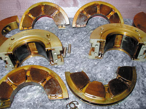
Figure 1. These heavy varnish deposits
were found on bearing surfaces.
(Courtesy Fluitec International)
If oil condition was the focus of monitoring rather than machine condition, then varnish likely would not progress to the point of accumulation and the oil would be much more capable of meeting its design. This type of lubricant condition monitoring should be emphasized when performing varnish-related monitoring since oil with a high varnish load can be expected to have critical loss in key design characteristics such as water separability and inhibiting corrosion/rust, foam and air release. Loss of any of these properties can place the system at significant risk. Testing criteria that focus on these properties should be at the forefront of the varnish issue.
Varnish Basics
The typical varnish progression begins with a reaction at the molecular level. This generally includes an oxygen molecule. In oil, the oxidized molecule is controlled through additives, which inhibit it from accelerating the degradation of the remaining oil. As more varnish forms, it becomes distinct particles that can be measured in nanometer-sized particles. As the numbers of these particles increase, this degradation material within the oil can be described as a varnish cloud of nanometer-sized material. When the cloud density oversaturates the oil, some of the varnish material will settle out within the lubrication system (like rain falling from the sky) in the form of a deposit. In time, the deposit can harden into a solid material, which is commonly known as varnish.
Oil Saturation
Turbine oil is designed to hold and manage a finite volume of varnish material. When this capacity is exceeded, the oil is considered saturated. Deposits can then form and accumulate in the system. Saturation has a relationship with temperature in that oil at a higher temperature is able to retain a greater volume of the nanometer-sized varnish material than oil at a lower temperature.
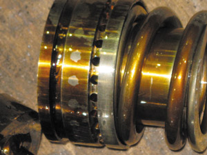
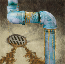
Figure 2. Varnish can occur in any system.
(Courtesy Paul Sly, Chevron)
The desired system condition for new oil would be to install the oil into a clean system so the progression of oil degradation and subsequent varnish accumulation would be limited to natural degradation of the oil. This degradation progression should be limited to the influences of new varnish created within the system as opposed to existing system varnish, which is known to accelerate oil oxidation.
It is important to install oil into a clean system so the maintenance sensitivity will more appropriately respond to the oil’s initial varnish saturation level as an oil failure criterion. This sensitivity should be maintained at the lowest expected system oil temperature rather than at a higher temperature, since deposits will form and collect in a system at this lower temperature, and deposit formation should be considered a lubricant failure mode.
Base Oil Influence
Varnish accumulation is also influenced by the base oil category, as designated by the American Petroleum Institute (API). Group II base oils have a superior design and can be expected to provide improved performance over Group I base oils, assuming that the system in which the oil is installed is clean. Both Group I and II base oils have inherent solvency, which means that they have a finite capacity to accumulate and hold varnish products. However, there is an important difference in how each does this. Due to the manufacturing process resulting in a more highly saturated molecule, Group II oils have less varnish-retention capacity than Group I oils. As such, Group II oils allow varnish deposits within a system to occur with a lower overall volume of the material present.
System Cleanliness
When a new charge of turbine oil is installed, it is vital that the system be clean and free of varnish. A common problem is that many existing systems are not cleaned prior to the installation of new/replacement oil. As mentioned previously, turbine oil has a natural design property that allows it to hold and accumulate varnish. In addition, existing system sludge and varnish that have adhered to surfaces within a turbine oil system are not readily dislodged with a system flush. As a result, when new, clean oil encounters this existing varnish within a system, it begins to chemically react with the varnish and remove this material from the walls, causing the new oil to approach a point of saturation.
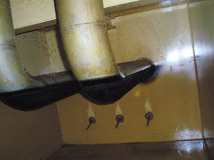
Figure 3. Varnish deposits were
found within this system.
Within a relatively short period of time, this “chemical cleaning” phenomenon can render the benefits of a new oil change moot in terms of oil performance and design. In other words, the removal of system varnish may reduce the new oil to a “failed oil” status not long after it is placed in service.
The same condition occurs after a varnish-saturated oil is cleaned of varnish residue, but the cleaning is stopped prior to the system itself becoming clean. The newly cleaned oil will again accumulate varnish materials from the system to once again approach saturation levels. Remember, varnish acts as a catalyst to speed oil and additive degradation. As such, operating with varnish within the oil allows new varnish to form more quickly and shortens the service life of the oil.
Complications/Variations
The consequences of accumulated varnish within a turbine system can include power de-rating and damage to the operating equipment. When observed problems begin to occur, the concentration of varnish within the oil or system can vary greatly. Factors such as system design, variations in the system operating temperature and fluctuations in the system operating conditions all affect varnish formation.
Systems that use turbine oil as control oil are highly susceptible to issues. The control systems include tight orifices located in lower temperature regions. These conditions allow hot, saturated oil to accumulate deposits at these important system locations.
The choice of oil also impacts the rate of varnish generation and accumulation, as some oils are more prone to varnish drop-out than others. Figure 4 shows two samples with similar laboratory settling times. While these oils have a highly similar visual appearance, they have dramatically differing levels of varnish load, which is related to the influence of oil additives, base oil and the chosen formulation.
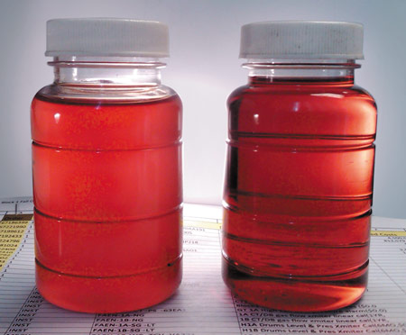
Figure 4. Different oil formulations can have very different
varnish conditions but appear highly similar.
(Courtesy Dave Wooton, Wooton Consulting)
Oils from different manufacturers are known to have different additives and base oils. Depending on the in-service operations, their differences can influence the severity of a developing varnish issue. Because these oil design variations are considered proprietary information by the lubricant manufacturers, the consumer of the oil is unlikely to be able to determine which oil formulation is least likely to cause varnish problems.
When system contaminants mix with the oil in service and further degrade it, the design properties such as water separation, foaming and the oil oxidation rate may be greatly compromised. As system design and operating conditions also vary, their impact should be considered as it relates to the select formula as well. This parameter of additive chemistry adds to existing varnish challenges for both oil performance and service life.
Laboratory Testing
The lubricant condition-monitoring community has developed a laboratory test (ASTM D7843) to assess the degree of accumulated varnish load within in-service oil. This Membrane Patch Colorimetry (MPC) test measures the overall load of varnish type material in the oil sample and includes a three-day settling period to allow varnish material to agglomerate within the oil, which is cooling from its operating temperature.
The oil is then filtered through a 0.45-micron cellulose patch with the aid of a solvent. Varnish material collects and deposits on the patch. The patch is checked for color, which is influenced by the volume of material deposited. A dark brown color is visible when more varnish from the fluid is on the patch surface.
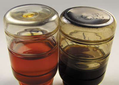
Figure 5. The MPC test measurement of the sample on the
left was 24, while the sample on the right measured 156.
(Courtesy Dave Wooton, Wooton Counsulting)
Figure 5 shows side-by-side examples of a split sample of turbine oil that was allowed to sit for a two-week settling time under controlled conditions. The sample on the left was stored in the dark, while the sample on the right was left in the sun. The contribution of the sun is the difference in these samples, which have different colors and very different varnish loads.
Alarm Limits and Criteria
The lubricant test community is currently using various versions of the color patch test to assess the volume of varnish within oil and the likelihood of damaging deposits occurring. Unfortunately, the test variations in use may scale the color differently and provide differing warning and alarm limits. These differences can lead to significant confusion in the marketplace.
In addition, current alarm limits and action criteria focus on the effect of varnish accumulation on lubricated machinery. This approach discounts the impact of varnish on the design and function of the oil as well as the potential effect of this material on other oil failure modes.
| 3 | days of settling is included in a Membrane Patch Colorimetry (MPC) test to allow varnish material to agglomerate within the oil, which is cooling from its operating temperature. |
A more fundamental approach to setting alarm and action limits that includes the impact of varnish on the oil’s performance is needed. The criteria should consider when the oil has lost its design performance, and these performance failure modes should be the point of initial action.
A temperature limit of oil saturation could become an important criterion. This could be measured by the patch test but at lower limits than those presently used in order to avoid machinery issues. This approach could then retain the present criteria as a higher severity warning for varnish and separate criteria for its potential challenge to machine operation.
Mitigation
Since oil that is in operation at a fully saturated level can be expected to leave varnish deposits, mitigation strategies to manage this condition should be directed at keeping varnish levels at a concentration where deposits would not be expected to form. The following are viable preventive maintenance strategies that have been demonstrated to benefit the system oil condition or varnish saturation level:
Partial or Full Oil Changes
As new oil does not have any retained varnish products, it would not be expected to cause new deposits when added to the system. However, the benefit of this method is severely limited by the quantity of varnish deposits within the system. When new (or newly cleaned) oil is placed in service, its inherent design results in cleaning the existing system varnish, which then goes into the oil. After this has occurred, the oil can again become saturated, and new varnish deposits can commence once saturation levels have been reached.
A secondary problem can develop from this mitigation strategy if varnish is removed from a less harmful area and then re-deposited in more undesirable locations. Another drawback in making frequent oil additions including full oil replacement involves the expense, as large volumes of oil can be costly.
While this approach could be beneficial if implemented in a manner that keeps the oil in a less than saturated condition, managing this would require frequent laboratory tests to ensure the oil condition. It is also questionable whether oil consumers would be sufficiently sensitive to the rate of varnish accumulation or change in the new oil to properly implement this method. However, it would produce a net benefit if performed periodically, as the cleanliness of the system in terms of existing varnish deposits can be improved with time.
Filtration with Cellulose Media
The best time to filter varnish material retained within oil is when the oil is at an ambient temperature for a few days. This allows the varnish to agglomerate and be collected by the filter material. Filter replacement is a must if this strategy is employed, as varnish material removed from the oil at ambient temperature returns to solution if the filter is not replaced prior to returning the oil to the higher operating temperature. This is due to the greater solvency of the oil at the higher operating temperature.
The primary limitation of this approach is that the filtration is limited to the reservoir oil and cannot be expected to reduce the volume of varnish within the main turbine system. When the oil returns to service, its inherent design is as a solvent, thus the results are removal of system varnish. Once again, due to existing system deposits, a saturation of the operating oil can reoccur.
In addition, varnish can migrate from a less harmful area to an undesirable location. The overall cost of this strategy can also be expensive, as frequent filter replacements could be required to remove system varnish from the varnish-laden filters. However, this method does produce a net benefit when performed periodically, and the cleanliness of the system in terms of varnish deposits can be improved.
System Chemical Cleaning
This method is the quickest way to improve system cleanliness and allow the oil to function as it was designed. While a clean system will extend the useful service of the new replacement oil, it cannot be expected to prevent reoccurrence of varnish. Its cost to implement can also be high.
Ion Filtration
With ion filtration, oil is processed through resin beads, which chemically attract the varnish component and remove it from the oil. This cleaning can occur at operating temperature. Ion filtration takes advantage of the oil’s design to slowly clean and remove existing varnish from the system as the oil is in service. With time, this process produces both a clean system and clean oil.
Conclusion
Mitigation strategies of ambient temperature filtration followed by filter replacement or installation of new oils can be used to manage varnish in systems if carefully employed. Of course, these strategies will carry the cost of additional oil and filter purchases. Regular laboratory testing also would be needed to manage these strategies and to monitor their effectiveness.
The introduction of Group II base oils as a fundamental component of turbine oils has not caused the varnish issues that plants are currently encountering, although their solvency and capacity to hold varnish were contributing factors. The change to a Group II base oil component has reduced the capacity of the fluid to retain varnish materials. Additional contributors include the formulation of the oil, the system design, the operating conditions and how much existing varnish is within the system.
| 81% | of lubrication professionals have experienced problems caused by oil degradation products such as varnish and oxidation, according to a recent poll at machinerylubrication.com |
A primary culprit of varnish problems occurring within industry can be directly attributed to the system cleanliness in terms of residual varnish deposits. The key to long-term varnish mitigation is in establishing a system free of varnish and then continuing a process that maintains both the oil and system in this condition. Ion filtration has been demonstrated to create these conditions, although once the system is clean, frequent oil additions or filter replacements may also be useful.
While the current industry focus regarding varnish has been on turbines, the same base oils and formulations are used for compressor, circulating and large motor/gearcase applications. Likewise, the same degradation mechanisms of the oil and additives would be present with subsequent varnish accumulations expected to occur. Such varnish deposits may be found on bearing and gear surfaces as well. Although the consequences of this accumulation and stress on oil properties have not been discussed, sensitivity to varnish should also be applied to these applications.
Alarm and action limits should be established to ensure system and oil cleanliness. This approach is challenged by long-standing plant operating expectations and experiences where varnish sensitivity was not required. The existing belief that there is an acceptable quantity of varnish within either the oil or system and that it is of no consequence must be overcome. Low action and alarm criteria should be set to protect the design and performance of the oil. In other words, a no-tolerance approach to varnish is required.
 The selection of breathers and monitoring breather condition provide another method of reducing ingression. Whether you are using them to eliminate dirt or water ingression, breathers are imperative for machine health. They must be selected according to the machinery conditions and environment. Frequently, breathers are not monitored properly. Like oil filters, they have an intended purpose and function well; however, once they reach the end of their life cycle, it is important to replace them promptly.