You may have read them at some point in your life that 50% start up companies doesn't go past the 5 years mark; up to 75% companies doesn't reach 10 years. Most of the more established companies also fail later in their life due to un-adaptability, which make the case for change a must!
I have walked into organisation with so much internal complains that it does themselves more harm than good. Do ask the complainers, are you part of the solution? If you're not, then you're part of the problem.
Complaining doesn't make a difference, if you don't make a difference to improve, then you are just part of the contributing problems.
First, the leader(s) would have to be a visionary. He would have to teach the organisation how to dream. Without a dream, without a vision, without knowing what they want to be and what they can be, they would not know how to get there.
Second, cost-cutting is so yester-years. Stop unnecessary cost-cutting. Invest in your people's development, coach the right leadership into them. Also, invest in implementation of efficient system that streamline and make work easier. Employees are your biggest asset, without them, your company is just a shell. Invest in them! Be very wary of managers who are cost-cutting experts, they are likely bringing the company to la-la land.
Third, remove those who don't embrace the improvement drive. Stop the blaming culture, stop it right there and then. Instill back ownership, instill back quality right from the top. It's not an employee's fault if he/she made a mistake, it's because your mismanagement of the system which allow him/her to make that mistake possible. In the era of huge generation gap, low population growth, high human resource turnover, the only thing that will stay there and do the job is the system. So it comes back again to invest on your system!
Fourth, reward competency, reward ownership, reward high-performance. Discourage blaming, discourage cost-cutting, and discourage poor workmanship. Only there and then, the hull will start to take a turn for the better.
Wednesday, 8 October 2014
Tuesday, 8 July 2014
Ensure Planning and Scheduling Success
Article extract from Reliable plant newsletter:
http://www.reliableplant.com/Read/28924/planning-scheduling-success
How do you initially train someone new to the planner/scheduler position? First, let’s talk about the selection process, as I see this as an issue in many organizations. Ideally, the planner/scheduler should be one of your best craftspeople. You have to compensate the position at a level at least equal to your first-level supervision. The compensation should include accounting for the average overtime earned as a craftsperson if you expect them to apply for the position. You will not get many applicants if you are asking them to accept a significant reduction in their pay.
In addition to being a highly skilled craftsperson, the candidate should have good computer skills, a positive attitude, people-oriented and be self-motivated.
After you have identified the right person, the obvious next step is to get that person trained. You generally have a couple of choices here. You can send them off to a class, or you can host an on-site course.
This brings us to another question. How do you help guarantee success with planning and scheduling? Realize that you can send a planner/scheduler off to training, have them return and, despite their best efforts, the organization will not allow them to plan and schedule work. Providing the on-site course will allow you to educate supervisors, team leaders, managers, engineering personnel, production supervisors, production planners and anyone else who interacts with the maintenance work management process. Now everyone can understand not only the roles and responsibilities of the planner/scheduler, but also their own roles and responsibilities in relationship to the work management process.
When I teach maintenance planning and scheduling classes, I want to share a number of approaches. There are a several methods and opinions on how to plan and schedule work. What I find is that some groups actually do a disservice to their course participants by not sharing a comprehensive approach with various methods.
After the initial training is complete, recognize that you are only one-third to halfway done. After about one to two months, it’s time to bring in a coach. Ideally, the coach is an external resource who walks a mile beside the new planner/scheduler. The purpose of this is to observe the activities of the planner/scheduler and also the interactions within the organization.
When I coach and mentor, I’m looking to determine if the planner/scheduler is applying the items learned in the class. Are they creating job plans? Is the continuous improvement loop in place? Is the planner/scheduler focused on the future?
Next, I’m looking to see how the supervisors are interacting. Do they understand their roles and the planner’s roles? Are work orders being completed and data entered into the CMMS? Is the organization aligned for proactive scheduling? These are just a few of the items that I address in my coaching sessions.
The number of coaching sessions depends on the organization. It may only be one to two in total. Now, about retraining, a number of organizations bring me back on a semi-annual to annual basis to provide an overall best practices health check as a good method to determine if the organization is continuing to mature in its implementation efforts. If it has gone stagnant, I’ll point out the obstacles and help get them back on the road to success. Ultimately, this is my primary goal. I have a passion for maintenance and operations, so I really care about people being successful.
If not an external resource, someone internally needs to remove the obstacles to ensure effective planning and scheduling.
With respect to retraining, you should always be in a state of constant learning. That means reading articles and attending events that foster learning.
During a two-day maintenance management course in California’s wine country, I met a planner/scheduler who attended the course the previous year. At the end of the course, I asked him why he chose to re-attend so soon afterward. He mentioned that he had forgotten a number of items, and the main one was creating job plans. Wow! Besides scheduling the work, this is one of the most important parts of planning and scheduling. This example highlights the need for retraining, especially if you opted not to provide coaching.
About the Author
Monday, 7 July 2014
Introduction to filters (Engine Oil Bypass Filtration)
Article extract from Reliable plant newsletter:
http://www.machinerylubrication.com/Read/29026/engine-bypass-filtration
Understanding Engine Oil Bypass Filtration
http://www.machinerylubrication.com/Read/29026/engine-bypass-filtration
Understanding Engine Oil Bypass Filtration
Is your engine’s oil filter performing to your expectation? Do you even know the performance of your filter? Most people don’t, and if they did, they would be appalled.
Some of the best full-flow engine filters on the market perform at a capture efficiency of 50 percent at a particle size of 10 microns and above. That’s a beta ratio of 2 for those of you keeping score, and these are considered “good” in terms of full-flow engine filtration. In comparison, a beta ratio of 1,000 would be considered “good” in terms of industrial hydraulic filtration. Why is there such a performance difference? The following factors contribute to the variance:
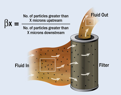
The beta ratio is calculated by dividing the number of particles larger than a certain size upstream of the filter by the number of particles of the same size downstream of the filter. For example, you may have a beta ratio or a beta sub 5 (meaning particles larger than 5 microns) equal to 10. This means 10 particles upstream of the filter would be divided by 1 downstream of the filter. In other words, for every 10 particles coming in, one gets through.
If you have a higher beta ratio, say a beta ratio of 100 or a beta sub 5 equal to 100, for every 100 particles coming into the filter larger than 5 microns, one makes its way through.
Every filter will have multiple beta ratios. There could be a beta ratio for 2 microns, 5 microns, 10 microns, 50 microns, 100 microns, etc.
 You can also use the beta ratio to calculate capture efficiency, which is the average performance over the filter’s life, with the following formula:
((Beta – 1)/Beta) x 100 As an example, a beta ratio of 10 would yield a capture efficiency of 90 percent:
((10 – 1) / 10) x 100 = 90 percent Therefore, 90 percent of the particles larger than 5 microns are removed by a filter that has a beta ratio of 10.
When these factors are combined, a problem arises. The physical size is usually constrained by design. The filter can’t be too large because of all the other components that we are trying to fit under the hood. The flow rate must be high enough to feed all the lubricated components. This means you can’t make the pore size too small or it will raise the pressure differential and the bypass valve will open, effectively rendering the filter useless.
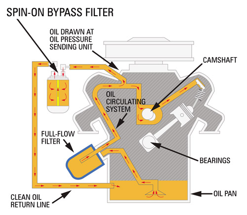
There are a few things you can do to remedy this problem. Enter bypass filtration. Bypass filtration systems take 5 to 10 percent of the flow that would have gone to feed the engine and cycle it through an ultra-efficient filter and back to the sump.
With bypass filtration, the flow rate can be greatly reduced, allowing for a much smaller pore size while retaining a normal pressure differential. The result is much cleaner oil being returned to the sump. Smaller soot suspension and polar insolubles that are not controlled by the full-flow filter can now be taken out of the system. When combined with a full-flow filter, bypass filtration offers the benefits of lower wear generation rates, lower oil consumption, higher combustion efficiency and longer oil life.
In a case study performed by General Motors and published by the Society of Automotive Engineers (SAE), it was determined that engine service life could be extended eight times when 5-micron filtration is implemented vs. the standard 40-micron filtration.
 Obviously, having cleaner oil is better for the reliability of the engine. There’s an old saying that oil doesn’t wear out; it just gets dirty. Although there is some validity to the idea that dirtier oil will “age” quicker than clean oil, the engine oil will have a finite life. It will need to be changed eventually no matter how clean you keep it.
While it’s true that a system can remove the majority of suspended soot, wear debris and dirt, the oil and additives are still being decomposed by oxidation and nitration. The depletion of these additives will ultimately be the reason for the oil change. The system should slow down the rate of this depletion, but it cannot eliminate it. Acids, fuel and coolant are just a few of the contaminants that bypass filtration cannot address. They too can shorten the life of the oil.
If you are shopping for one of these systems, it is vital that you do your homework. Not all bypass systems are created equal, and there is a plethora of marketing material out there to make you feel thoroughly confused. Keep in mind that while testimonials may seem impressive, they are not scientific proof. Make sure the manufacturer has SAE and ISO testing to back up its claims.
When installed and maintained properly, a bypass system can provide great benefits. Just be sure to ask all the right questions and have a firm grasp on the concept before settling on a system.
About the Author
Some of the best full-flow engine filters on the market perform at a capture efficiency of 50 percent at a particle size of 10 microns and above. That’s a beta ratio of 2 for those of you keeping score, and these are considered “good” in terms of full-flow engine filtration. In comparison, a beta ratio of 1,000 would be considered “good” in terms of industrial hydraulic filtration. Why is there such a performance difference? The following factors contribute to the variance:
Physical Size
Often limited by physical size, engine oil filters are relatively small when compared to their industrial counterparts. This small size coincides with less filter media surface area through which to pass the lubricant.| 65% | of lubrication professionals use bypass filtration systems at their plant, based on a recent poll at machinerylubrication.com |
Pressure Differential
The pressure differential is the change in pressure from the inlet to the outlet side of the filter. If the pressure differential is too high, a valve will open, allowing the oil to bypass the filter. All engine oil filters or heads are equipped with a bypass valve. This valve is needed so the engine does not become starved of oil as the filter clogs with debris.The Beta Ratio Test
Oil filters can be tested in a variety of ways, but one of the most common methods is the beta ratio test. This test incorporates online particle counters positioned upstream and downstream of the filter, a continuous flow of test contaminant into the main system reservoir and oil flowing through the filter.The beta ratio is calculated by dividing the number of particles larger than a certain size upstream of the filter by the number of particles of the same size downstream of the filter. For example, you may have a beta ratio or a beta sub 5 (meaning particles larger than 5 microns) equal to 10. This means 10 particles upstream of the filter would be divided by 1 downstream of the filter. In other words, for every 10 particles coming in, one gets through.
If you have a higher beta ratio, say a beta ratio of 100 or a beta sub 5 equal to 100, for every 100 particles coming into the filter larger than 5 microns, one makes its way through.
Every filter will have multiple beta ratios. There could be a beta ratio for 2 microns, 5 microns, 10 microns, 50 microns, 100 microns, etc.
((Beta – 1)/Beta) x 100 As an example, a beta ratio of 10 would yield a capture efficiency of 90 percent:
((10 – 1) / 10) x 100 = 90 percent Therefore, 90 percent of the particles larger than 5 microns are removed by a filter that has a beta ratio of 10.
Flow Rate
In most engine designs, oil must flow through the filter before entering the engine components. Therefore, the filter must be able to handle 100 percent of the flow rate needed to feed the moving components of the engine.Media Pore Size
The media pore size is the major determinant in how efficient and how small of a particle the filter can remove.When these factors are combined, a problem arises. The physical size is usually constrained by design. The filter can’t be too large because of all the other components that we are trying to fit under the hood. The flow rate must be high enough to feed all the lubricated components. This means you can’t make the pore size too small or it will raise the pressure differential and the bypass valve will open, effectively rendering the filter useless.
There are a few things you can do to remedy this problem. Enter bypass filtration. Bypass filtration systems take 5 to 10 percent of the flow that would have gone to feed the engine and cycle it through an ultra-efficient filter and back to the sump.
With bypass filtration, the flow rate can be greatly reduced, allowing for a much smaller pore size while retaining a normal pressure differential. The result is much cleaner oil being returned to the sump. Smaller soot suspension and polar insolubles that are not controlled by the full-flow filter can now be taken out of the system. When combined with a full-flow filter, bypass filtration offers the benefits of lower wear generation rates, lower oil consumption, higher combustion efficiency and longer oil life.
In a case study performed by General Motors and published by the Society of Automotive Engineers (SAE), it was determined that engine service life could be extended eight times when 5-micron filtration is implemented vs. the standard 40-micron filtration.
While it’s true that a system can remove the majority of suspended soot, wear debris and dirt, the oil and additives are still being decomposed by oxidation and nitration. The depletion of these additives will ultimately be the reason for the oil change. The system should slow down the rate of this depletion, but it cannot eliminate it. Acids, fuel and coolant are just a few of the contaminants that bypass filtration cannot address. They too can shorten the life of the oil.
If you are shopping for one of these systems, it is vital that you do your homework. Not all bypass systems are created equal, and there is a plethora of marketing material out there to make you feel thoroughly confused. Keep in mind that while testimonials may seem impressive, they are not scientific proof. Make sure the manufacturer has SAE and ISO testing to back up its claims.
When installed and maintained properly, a bypass system can provide great benefits. Just be sure to ask all the right questions and have a firm grasp on the concept before settling on a system.
About the Author
Jeremy Wright is a Senior Technical Consultant for Noria Corporation. Hire Jeremy to develop procedures for your lubrication program or to train your team on machinery lubrication best practices. ... Read More
Starting & Maintaining CMMS
Most organisation nowadays would start the CMMS setup in parallel with the project they run. Regardless of brownfield or greenfield, the first phase of the CMMS setup is the data entry upon finalizing the master equipment list. Below is two article by Kris Bagadia in regards to CMMS Data Entry and Training. It highlights the importance of utilizing technical person for the job.
When implementing a computerized maintenance management system (CMMS) into a facility, one of the largest tasks involved is entering the data into the system. This is a two-part task that first requires the one-time entry of the initial data that has been gathered. The second task is the entry of the ongoing information required to use the CMMS to its full potential.
Initial data entry is a large task, but making a good commitment to the initial data gathering will make the job easier.
There is a massive amount of work required between gathering and entering this initial data. After all, there will be equipment data such as model number, serial number, equipment ID, purchase date, installation date, warranty, etc. Included in the data should be information on preventive maintenance on each asset (what needs to be done, how often work should be performed, etc.). There will also be inventory parts information including part number, description, location and reorder point. Labor information including each technician’s name and basic employee information also should be incorporated.
Make forms to collect all the data you are planning on entering into the CMMS, have technicians fill out these forms, and then decide on a data-entry method. Who will do this job? There are three basic options that can be considered.
Using your current employees to enter in the data will work if you have committed them to this project. Using them on a “need basis” doesn’t work effectively. Temporary employees are cost-effective and work well especially if the initial data gathering provides them with clearly filled-out forms to follow. Turnkey operations complete the entire implementation process from start-to-finish. Each has its pros and cons, and only you can decide which is best for your situation.
Next, you need to determine what will be the best method of entering in the necessary day-to-day information that the CMMS will manage. Every time a technician completes a job, the information regarding the actual job done, the amount of time it took, specific parts used and any additional details the technician includes will need to be entered into the system. The two most common methods include having an administrative assistant enter in all of the information or having each technician enter in the information.
One big misconception is the thought that having one person do the data entry (such as an administrative assistant) will save time and money in the long run. After all, having one person spend one day a week entering in all the information seems easier than having 20 maintenance technicians spend five to 15 minutes entering in each of their information daily.
However, by having an administrative assistant enter in the data, this requires the technician to record everything on paper. In addition, the time required for the technician to correctly fill out the paper and submit to the administrative assistant could have been used to simply enter the information directly into the system.
The information may be illegible due to handwriting or environmental issues such as oil or grease getting on the paper. The paper may even get lost. At this point, the administrative assistant will need to track down the appropriate technician (which may not be an easy task) to get the correct data. Valuable time is wasted because of the process in place. Or, perhaps the data is just entered incorrectly because of guesswork or frustration. By using paper, there could easily be a backlog of documents that need to be entered, which can lead to inaccurate data analysis as the data is not current.
Having the technicians enter in the information themselves allows quicker access to data in the system. The time required to document the data is reduced, along with paperwork. The information is also fresh in their mind and potentially more technically correct than if an administrative assistant is entering in recorded data. One concern employers have is giving technicians the freedom to use computers. That “freedom” is misused sometimes by the technicians who stay on the computers for hours when entering data should only take a few minutes. But, with the proper supervision and training, this concern can easily be negated.
Having a solid plan for how to enter initial data into the system, as well as managing the ongoing data entry requirements, will deter confusion later. Review your work process flow carefully to decide the best method that will work in your situation.
When the setting up phase is done, the maintenance phase requires continuous training and awareness program as well. Part 2 of this entry is another article from Kris.
Training for users of a computerized maintenance management system (CMMS) is a multiple-phase process. There are three areas of training needs: basic training, application (CMMS) training and internal training.
For instance, take equipment numbering schemes. CMMS users should be trained on numbering schemes to avoid erroneous data entry.
Another good example is inventory part description. If part description data entry is not consistent, you will find a corrupt inventory database after a while.
Work order data entry is another example. Descriptions such as “machine down” or “doesn’t work,” followed by a repair description of “done” or “fixed,” will not give you meaningful history. Therefore, proper and consistent job description training is important.
Basic Training
Make sure people who will operate the CMMS are familiar with computer basics and the operating system. If not, provide them with basic training so they are ready for CMMS application training.Application (CMMS) Training
This can be done in two different phases — initial training to get the system up and running, and advanced training after spending a period of time with the CMMS. Long training (five to 10 days) is not recommended, since most people forget the majority of the items learned. Timing of the training should be kept in mind. Don’t train too early in the day. Training should be coordinated with implementation. Trainees should leave the class and use what they have learned immediately.Internal Training
You also need to train CMMS users with internal processes. This is often ignored in most CMMS implementation projects. Your software vendor will only train you on how the CMMS application works. You have to do the internal training yourself.For instance, take equipment numbering schemes. CMMS users should be trained on numbering schemes to avoid erroneous data entry.
Another good example is inventory part description. If part description data entry is not consistent, you will find a corrupt inventory database after a while.
Work order data entry is another example. Descriptions such as “machine down” or “doesn’t work,” followed by a repair description of “done” or “fixed,” will not give you meaningful history. Therefore, proper and consistent job description training is important.
General Training Guidelines
- Be sure that every trainee is given enough help to become comfortable and confident in what he or she is doing. Even a small shortage of needed training can cause an employee to backslide, lose confidence and eventually cause project failure. The new system cannot afford that. All personnel who will use the CMMS, maintain it or oversee its operation should be included in the training process.
- Accept any and all training support from your vendor. You may wish to contract with your vendor for additional training support or follow-up training programs or services. Remember, while the training initially may seem like an expensive proposition, in the long run it will not only prove beneficial but also very cost effective.
- Training should be an ongoing process. New users should receive the full course, while current users should take refreshers as needed or desired. This continuity will accommodate the inevitable personnel changes and system evolutions that will occur over the life of the system. As users leave, their replacements must be trained as thoroughly as if they had been original users. This need is frequently overlooked.
- During the training process, the newly installed CMMS can be checked thoroughly to assure that it works as planned. Feedback from trainees should be recorded and analyzed to assist in evaluating system performance and potential modification. Action on trainee responses not only will result in system refinements but also will improve the general acceptance of the CMMS.
Thursday, 3 July 2014
The Hidden Dangers of Lubricant Starvation
Article extract from Reliable plant newsletter:
http://www.machinerylubrication.com/Read/29040/lubricant-starvation-dangers
 For those who strive for lubrication-enabled reliability (LER), more than 95 percent of the opportunity comes from paying close attention to the “Big Four.” These are critical attributes to the optimum reference state (ORS) needed to achieve lubrication excellence. The “Big Four” individually and collectively influence the state of lubrication, and are largely controllable by machinery maintainers. They are well-known but frequently not well-achieved. The “Big Four” are:
Over the past few decades, researchers and tribologists have compiled countless listings that rank the chief causes of machine failure. We’ve published many of these in Machinery Lubrication magazine. The lists ascribe the causes of abnormal machine wear to the usual suspects: contamination, overheating, misalignment, installation error, etc. There’s typically a lubrication root-cause category that is a catch-all for one or more causes that can’t be easily specified or named. I’ve seen terms used like “inadequate lubrication” and “wrong lubrication.”
Understandably, it is difficult for failure investigators and analysts to trace back the exact sequence of events beginning with one or more root causes. Evidence of these causes is often destroyed in the course of failure or in a cover-up during the cleanup and repair. Having led several hundred such investigations over the years, I’ve learned that one root cause in particular is too often overlooked - lubricant starvation.
Although most everyone knows about this in principle and realizes the common sense of adequate lubricant supply, it is frequently ignored because many typical forms of lubricant starvation are largely hidden from view. For instance, who notices the quasi-dry friction that accelerates wear each time you start an automobile engine? This is a form of lubricant starvation. It’s not a sudden-death failure, but it is a precipitous wear event nonetheless. Each time controllable wear goes uncontrolled, an opportunity is lost to prolong service life and increase reliability.
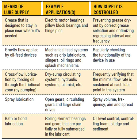
The table below illustrates how lubricants reach frictional surfaces in numerous ways.
 There are six primary functions of a lubricating oil. These are friction control, wear control, temperature control, corrosion control, contamination control and transmittance of force and motion (hydraulics). Each of these functions is adversely influenced by starvation conditions. The worst would be friction, wear and temperature control. Even partial starvation intensifies the formation of frictional heat. It also slows the transport of that heat out of the zone. This is a compounding, self-propagating condition that results in collapsed oil films, galling, adhesive wear and abrasion (Figure 1).
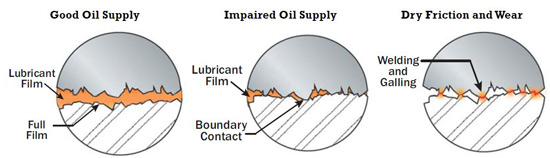
Figure 1. Starvation Illustrated
In the case of grease, starvation-induced heating (from friction) of the load zone accelerates grease dry-out, which escalates starvation further. Heat rapidly drains oil out of the grease thickener, causing volatilization and base oil oxidation, all of which contributes to hardening and greater starvation.
Lubricating oil needs reinforcement, which is lost when flow becomes restricted or static. Flow brings in bulk viscosity for hydrodynamic lift. In fact, lack of adequate lubricant supply is functionally equivalent to inadequate viscosity from the standpoint of film strength.
Oil flow also refreshes critical additives to the working surfaces. This reserve additive supply includes anti-wear additives, friction modifiers, corrosion inhibitors and others. Lubricant starvation produces elevated heat, which rapidly depletes additives.
Next, we know that wear particles are also self-propagating. Particles make more wear particles by three-body abrasion, surface fatigue and so on. Impaired oil flow inhibits the purging of these particles from the frictional zones. The result is an accelerated wear condition.
Finally, moving oil serves as a heat exchanger by displacing localized heat generated in load zones outward to the walls of the machine, oil reservoir or cooler. The amount of heat transfer is a function of the flow rate. Starvation impairs flow and heat transfer. This puts increasing thermal stress on the oil and the machine.
Precision lubrication supply is a fundamental attribute of the optimum reference state and is included in any engineering specification for lubrication excellence. It’s one of the “Big Four” and thus is overdue for significant attention.
About the Author
Jim Fitch
Jim Fitch, a founder and president of Noria Corporation, has a wealth of experience in lubrication, oil analysis, and machinery failure investigations. He has advised hundreds of companies on ... Read More
http://www.machinerylubrication.com/Read/29040/lubricant-starvation-dangers
- Correct lubricant selection
- Stabilized lubricant health
- Contamination control
- Adequate and sustained lubricant level/supply
Over the past few decades, researchers and tribologists have compiled countless listings that rank the chief causes of machine failure. We’ve published many of these in Machinery Lubrication magazine. The lists ascribe the causes of abnormal machine wear to the usual suspects: contamination, overheating, misalignment, installation error, etc. There’s typically a lubrication root-cause category that is a catch-all for one or more causes that can’t be easily specified or named. I’ve seen terms used like “inadequate lubrication” and “wrong lubrication.”
Understandably, it is difficult for failure investigators and analysts to trace back the exact sequence of events beginning with one or more root causes. Evidence of these causes is often destroyed in the course of failure or in a cover-up during the cleanup and repair. Having led several hundred such investigations over the years, I’ve learned that one root cause in particular is too often overlooked - lubricant starvation.
| 81% | of lubrication professionals have seen the effects of lubricant starvation in the machines at their plant, according to a recent survey at machinerylubrication.com |
The Nature of Lubricant Starvation
Machines don’t just need some lubricant or any lubricant. Rather, they need a sustained and adequate supply of the right lubricant. Adequate doesn’t just mean dampness or the nearby presence of lubricant. What’s defined as adequate varies somewhat from machine to machine but is critical nonetheless. High-speed equipment running at full hydrodynamic film has the greatest lubricant appetite and is also the most punished when starved. Machines running at low speeds and loads are more forgiving when lube supply is restricted. Even these machines can fail suddenly when severe starvation occurs.The table below illustrates how lubricants reach frictional surfaces in numerous ways.
Figure 1. Starvation Illustrated
Lubricating oil needs reinforcement, which is lost when flow becomes restricted or static. Flow brings in bulk viscosity for hydrodynamic lift. In fact, lack of adequate lubricant supply is functionally equivalent to inadequate viscosity from the standpoint of film strength.
4 Keys to Solving Starvation Problems Using Proactive Maintenance
- Identify the required lube supply or level to optimize reliability.
- Establish and deploy a means to sustain the optimized supply or level.
- Establish a monitoring program to verify the optimized supply or level is consistently achieved.
- Rapidly remedy non-compliant lube supply or level problems.
Next, we know that wear particles are also self-propagating. Particles make more wear particles by three-body abrasion, surface fatigue and so on. Impaired oil flow inhibits the purging of these particles from the frictional zones. The result is an accelerated wear condition.
Finally, moving oil serves as a heat exchanger by displacing localized heat generated in load zones outward to the walls of the machine, oil reservoir or cooler. The amount of heat transfer is a function of the flow rate. Starvation impairs flow and heat transfer. This puts increasing thermal stress on the oil and the machine.
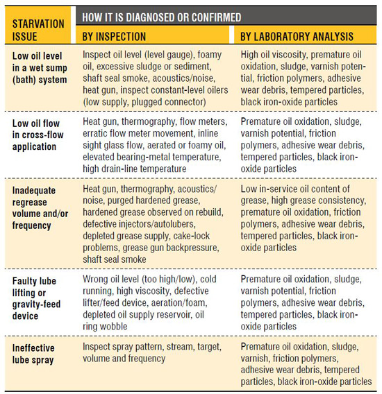
Common Signs of Starvation
When you’re encountering chronic machine reliability problems, think through the “Big Four” and don’t forget about No. 4. It may not be the type of oil, the age of the oil or even the contamination in the oil, but rather the quantity of oil. How can you know? The chart on page 8 reveals some common signs of lubricant starvation.Lubricant Starvation Examples by Machine Type
Lubricant starvation can happen in a number of ways. Most are controllable, but a few are not. The following abbreviated list identifies how lubricant starvation occurs in common machines.Starved Engines
- Dry Starts - Oil drains out down to the oil pan when the engine is turned off. On restart, frictional zones (turbo bearings, shaft bearings, valve deck, etc.) are momentarily starved of lubrication (Figure 2).
Figure 2. Dry Engine Starts - Cold Starts - Cold wintertime conditions slow the movement of oil in the engine during start-up. This can induce air in the flow line due to cold-temperature suction-line conditions.
- Low Oil Pressure - This can result from numerous causes, including worn bearings, pump wear, sludge and extreme cold. Oil pressure is the motive force that sends oil to the zones requiring lubrication.
- Dribbling Injectors - Fuel injector problems can wash oil off cylinder walls and impair lubrication between the piston/rings and the cylinder wall.
Common Signs of Lubricant Starvation - Clogged Spray Nozzles and Orifices - Nozzles and orifices direct oil sprays to cylinder walls, valves and other moving components. Sludge and contaminants are able to restrict oil flow.
Starved Journal and Tilting-Pad Thrust Bearings
- Oil Groove Problems - Grooves and ports channel oil to the bearing load zones. Grooves become clogged with debris or sludge, restricting oil flow.
- Restricted Oil Supply - Pumping and oil-lifting devices can become mechanically faulty. This also may be due to low oil levels, high viscosity, aeration/foam and cold temperatures.
- Sludge Dam on Bearing Leading Edge - Sludge can build up on the bearing’s leading edge and restrict the oil supply.
Wet-Sump Bearing and Gearbox Starvation
- Oil Level - Many wet-sump applications require critical control of the oil level (Figure 3).
Figure 3. Common Splash Gear Drive - High Viscosity - Many oil-feed mechanisms (oil rings, slingers, splash feeders, etc.) are hampered by viscosity that is too high (wrong oil, cold oil, etc.). Gears can channel through thick, cold oil, interfering with splash and other feed devices.
- Aeration and Foam - Air contamination dampens oil movement and impairs the performance of oil-feed devices (Figure 4).
Figure 4. How Aeration Retards Oil Supply - Non-horizontal Shafts - This can cause drag on oil rings and may interfere with slinger/flinger feed mechanisms.
- Bottom Sediment and Water (BS&W) - Sump BS&W displaces the oil level. On vertical shafts, the bottom bearing can become completely submerged in BS&W.
- Defective Constant-Level Oilers - This may be due to plugged connecting pipe nipples, mounting errors (tilted, cocked, mounted on wrong side, etc.), wrong level setting, empty reservoir, etc. (Figure 5).
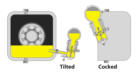
Figure 5. Mounting Errors of Constant-Level Oilers - Defective Level Gauge Markings - Level gauges should be accurately calibrated to the correct oil level.
- Level Gauge Mounting and Viewing Issues - These may be hard to see, goosenecks, fouled gauge glass, gauge vent problems, etc. (Figure 6).
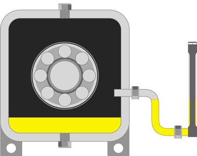
Figure 6. What is wrong with this picture?
Starved Dry-Sump Circulating Systems
- Restricted Oil Returns - Plugged or partially plugged oil returns will redirect oil flow away from the bearing or gearbox being lubricated. Sometimes called drip-and-burn lubrication, the condition is usually caused by sludge buildup or air-lock conditions in the gravity drain lines returning to the tank.
- Worn Oil Pump - When oil pumps wear, they lose volumetric efficiency (flow decay results).
- Restricted Pump Suction Line - Strainers and pickup tubes can become plugged or restricted. This can aerate the fluid, cause cavitation and lead to loss of prime.
- Clogged/Restricted Oil Ways and Nozzles - Oil-feed restrictions due to sludge, varnish and jammed particles can starve bearings and gears (Figure 7).
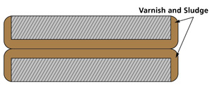
Figure 7. Plugged Oil Flow - Entrained Air and Foam - Oil pumps and flow meters perform poorly (or not at all) when sumps become contaminated with air (Figure 4).
- Lack of Flow Measurement - Components sensitive to oil supply require constant oil flow measurement.
- Defective or Miscalibrated Flow Meters - Flow meters, depending on the type and application, can present a range of problems regarding calibration.
- Low Oil Pressure - Oil follows the path of least resistance. Line breaks and open returns starve oil from higher resistance flow paths and the machine components they serve.
Starved Spray-Lubed Chains and Open Gears
- Defective Auto-lube Settings - This relates to correctly setting the lube volume and frequency.
- Defective Spray Targets/Pattern - The oil spray needs to fully wet the target location. Spray nozzles can lose aim and become clogged (Figure 8).
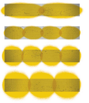
Figure 8. Correct Lubricant Spray Patterns
on Open-Gear Tooth Flanks - Gummed Chain Joints - Many chains become heavily gummed, which prevents oil from penetrating the pin/bushing interface.
Starvation from Grease Single- and Multi-Point Auto Lubrication
- Wrong Regrease Settings - Regreasing settings should enable adequate grease replenishment at each lube point.
- Cake-Lock - This occurs when grease is being pumped. Under certain conditions, the grease thickener movement is restricted. Oil flows, but the thickener is log-jammed in a line or component passage (Figure 9).
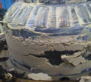
Figure 9. Cake-Lock
Grease Starvation - Defective Injector Flow - This is due to wrong injector settings or restricted injector displacement.
- Restricted Line Flow - Exceedingly long lines, narrow lines, numerous bends, ambient heat or cold, etc., can lead to partial or complete blockage of grease flow.
- Single-point Lubricator Issues - These include malfunctioning lubricators from various causes.
Starvation from Manual Lubrication Issues
- Grease Gun Lubrication - This may include an inaccurate volume calibration, a faulty grease gun mechanism, the wrong relube frequency, an incorrect relube volume or an improper relube procedure.
- Manual Oil Lubrication - This would include the wrong relube frequency, volume or procedure.
- Lube Preventive Maintenance (PM) - Missed PMs may be due to scheduling, management or maintenance culture issues.
The Crux of the Problem
Lubricant starvation is an almost silent destroyer. While there are telltale signs, they generally aren’t recognized or understood. Of course, there are varying degrees of starvation. Complete starvation is sudden and blatant. However, more moderate partial starvation is what tends to go unnoticed until failure. Then, other suspect causes (the bearing, lubricant, operator, etc.) may be falsely blamed.Precision lubrication supply is a fundamental attribute of the optimum reference state and is included in any engineering specification for lubrication excellence. It’s one of the “Big Four” and thus is overdue for significant attention.
About the Author
Jim Fitch
Jim Fitch, a founder and president of Noria Corporation, has a wealth of experience in lubrication, oil analysis, and machinery failure investigations. He has advised hundreds of companies on ... Read More
A benchmark for the flexibility and adaptability of maintenance management system
Article below was extracted from:
http://www.reliableplant.com/Read/28900/condition-monitoring-saving
Although the content is suppose to focus on the advantages of good condition monitoring, but pay attention to how maintenance parameters such as criticality, priority and frequency changes dynamically. Notice also the flexibility and adaptability of their system to cope with the dynamism. That is what I would consider a World Class Maintenance practice.
Saving Time and Money with Condition Monitoring
A recent acoustic emission (AE) study identified a potential critical bearing failure that became a planned preventive action for a leading food manufacturer. This also avoided considerable cost and unplanned downtime.
The acoustic emission equipment and the main tool used during the planned inspection routes were manufactured by Holroyd Instruments. This example will show the value of this type of equipment in avoiding a major unplanned event that could have had massive cost consequences for the business. Collateral damage to the associated equipment would have proved very costly, and the lead time to rebuild could have caused extensive downtime that would have meant disgruntled customers not being able to rely on stock availability.
The story began in April 2010 when some initial elevated readings were noted at two node points on a large step-down transfer gearbox that were sampled on a seven-day routine. The distress readings were elevated and triggered the alarm level. They were of concern and evident on subsequent inspections. The third elevated reading that was part of an upward trend instigated a planned work order in the computerized maintenance-management system (CMMS) to investigate and take further action. This equipment could not be taken out of service lightly, as it was at the time constrained by high production demands. Experience with a sister line’s previous planned bearing change also played an important part in the escalation of the risk.
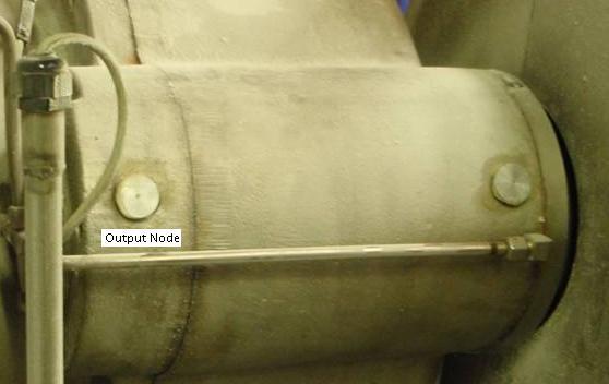
The input side of a transfer gearbox is shown with the output bearing node point on the left-hand side.
On more detailed inspections, it was determined that the bearing with the highest distress was indeed the suspected output bearing. Audible clicks were loud and clear at the output end bearing. The two bearings at the node locations were on the drive line of the motor at the input and output ends of the transfer gearbox. The adjacent bearings on the large, helical step-down gear were still reading low and had no audible clicks. The engineering manager was advised that there was an anomaly on one of the input bearings, that the others were in good condition and that production could continue with targeted condition monitoring. The routine oil sampling was increased from monthly to every two weeks. AE inspections were increased, with spectrum readings now on a four-day cycle. This would give some comparative evidence when the new bearings were eventually fitted.
The planned change of the bearing set was arranged with the production planner, maintenance manager and product specialist. It became clear that the equipment would have to operate for at least another six months until it became available. Contingency plans were formulated for an emergency change if any of the AE readings or oil samples showed advances toward failure. Warnings were issued that this could occur rapidly if the bearing failed. A new bearing set was purchased, and a meeting was scheduled with the bearing manufacturer to examine the used bearings when they were eventually changed in early 2011.
The AE readings stayed at an elevated level during this long waiting phase, and oil sample results showed no elevated readings in the key elements associated with roller bearing failures. During the weeks before renewal, many spectra were taken from all points of the gearbox for future evaluation. This would rule out frequencies from the oil pump and other components around the assembly. An AE envelope spectrum graph before the bearing change is shown below.
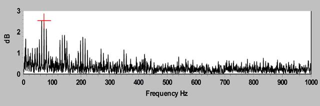
As can be seen, there was something creating a spike at 73Hz, which happened to match the frequency of the bearing race. This provided a clue that there was a race surface defect of some kind and not an element breaking down or the cage disintegrating.
The bearing change finally took place, and the production plant was turned around within 12 hours so that the equipment did not incur any unplanned downtime. The used bearing set was returned with the transfer gearbox, and the two units were degreased. On first inspection, they both looked similar and in good order. The elements and cages were then dismantled from the outer and inner races, with care taken to keep them in order and in the correct aspect for reassembly later.
It became clear that on the suspect output bearing, a major spall on the inner race had developed, and every element was pitted with the debris that had emitted. At this point, a representative from the bearing manufacturer was invited to visit and examine the bearings. He concurred that the bearings had lasted very well considering the atmosphere and heat in which they had operated for almost 10 years. This would be considered an end-of-lifetime mode of failure. It may have lasted many more months or could have accelerated to failure within days or weeks. The photograph below is of the spall that measured approximately 10 mm in length and 2.5 mm wide.
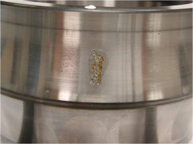
Spall damage to the race is shown above with feathered edges and surface pitting in the loaded area of the spalling. Note the next layer of material on the right-hand side that would have given way.
When the remedial work had been completed, additional spectrum samples were recorded and monitored to learn more. Carpet noise levels were lower, and the decibel scale was a third of the previous graph example. The maximum peak was now less than 0.4 decibels, while the carpet level was less than 0.2 decibels.
In conclusion, the systems and tools relied on every day proved effective in capturing this anomaly before it turned into a major event. The key to this was the full involvement of engineering with operations to plan in the remedial work with as little disruption as possible.
Among the lessons learned were that the inspection frequencies at seven-day intervals were correct for this critical plant, the preventive action was started at the earliest opportunity, the equipment enabled the pinpointing of the bearing fault, the audio facility allowed a second reference that linked rpm with the audible clicks and that this all gave sufficient evidence for the planned work to commence at the earliest opportunity.
Root-cause analysis was carried out directly after the bearing change was completed to investigate any future recommendations for servicing this equipment. It was decided that as the bearings had reached their end-of-life cycle, there was no need to alter any future planned maintenance. Condition monitoring with AE had provided the confidence to pick up any anomalies at a very early stage in the curve.
The acoustic emission equipment and the main tool used during the planned inspection routes were manufactured by Holroyd Instruments. This example will show the value of this type of equipment in avoiding a major unplanned event that could have had massive cost consequences for the business. Collateral damage to the associated equipment would have proved very costly, and the lead time to rebuild could have caused extensive downtime that would have meant disgruntled customers not being able to rely on stock availability.
The story began in April 2010 when some initial elevated readings were noted at two node points on a large step-down transfer gearbox that were sampled on a seven-day routine. The distress readings were elevated and triggered the alarm level. They were of concern and evident on subsequent inspections. The third elevated reading that was part of an upward trend instigated a planned work order in the computerized maintenance-management system (CMMS) to investigate and take further action. This equipment could not be taken out of service lightly, as it was at the time constrained by high production demands. Experience with a sister line’s previous planned bearing change also played an important part in the escalation of the risk.
The input side of a transfer gearbox is shown with the output bearing node point on the left-hand side.
On more detailed inspections, it was determined that the bearing with the highest distress was indeed the suspected output bearing. Audible clicks were loud and clear at the output end bearing. The two bearings at the node locations were on the drive line of the motor at the input and output ends of the transfer gearbox. The adjacent bearings on the large, helical step-down gear were still reading low and had no audible clicks. The engineering manager was advised that there was an anomaly on one of the input bearings, that the others were in good condition and that production could continue with targeted condition monitoring. The routine oil sampling was increased from monthly to every two weeks. AE inspections were increased, with spectrum readings now on a four-day cycle. This would give some comparative evidence when the new bearings were eventually fitted.
The planned change of the bearing set was arranged with the production planner, maintenance manager and product specialist. It became clear that the equipment would have to operate for at least another six months until it became available. Contingency plans were formulated for an emergency change if any of the AE readings or oil samples showed advances toward failure. Warnings were issued that this could occur rapidly if the bearing failed. A new bearing set was purchased, and a meeting was scheduled with the bearing manufacturer to examine the used bearings when they were eventually changed in early 2011.
The AE readings stayed at an elevated level during this long waiting phase, and oil sample results showed no elevated readings in the key elements associated with roller bearing failures. During the weeks before renewal, many spectra were taken from all points of the gearbox for future evaluation. This would rule out frequencies from the oil pump and other components around the assembly. An AE envelope spectrum graph before the bearing change is shown below.
As can be seen, there was something creating a spike at 73Hz, which happened to match the frequency of the bearing race. This provided a clue that there was a race surface defect of some kind and not an element breaking down or the cage disintegrating.
The bearing change finally took place, and the production plant was turned around within 12 hours so that the equipment did not incur any unplanned downtime. The used bearing set was returned with the transfer gearbox, and the two units were degreased. On first inspection, they both looked similar and in good order. The elements and cages were then dismantled from the outer and inner races, with care taken to keep them in order and in the correct aspect for reassembly later.
It became clear that on the suspect output bearing, a major spall on the inner race had developed, and every element was pitted with the debris that had emitted. At this point, a representative from the bearing manufacturer was invited to visit and examine the bearings. He concurred that the bearings had lasted very well considering the atmosphere and heat in which they had operated for almost 10 years. This would be considered an end-of-lifetime mode of failure. It may have lasted many more months or could have accelerated to failure within days or weeks. The photograph below is of the spall that measured approximately 10 mm in length and 2.5 mm wide.
Spall damage to the race is shown above with feathered edges and surface pitting in the loaded area of the spalling. Note the next layer of material on the right-hand side that would have given way.
When the remedial work had been completed, additional spectrum samples were recorded and monitored to learn more. Carpet noise levels were lower, and the decibel scale was a third of the previous graph example. The maximum peak was now less than 0.4 decibels, while the carpet level was less than 0.2 decibels.
In conclusion, the systems and tools relied on every day proved effective in capturing this anomaly before it turned into a major event. The key to this was the full involvement of engineering with operations to plan in the remedial work with as little disruption as possible.
Among the lessons learned were that the inspection frequencies at seven-day intervals were correct for this critical plant, the preventive action was started at the earliest opportunity, the equipment enabled the pinpointing of the bearing fault, the audio facility allowed a second reference that linked rpm with the audible clicks and that this all gave sufficient evidence for the planned work to commence at the earliest opportunity.
Root-cause analysis was carried out directly after the bearing change was completed to investigate any future recommendations for servicing this equipment. It was decided that as the bearings had reached their end-of-life cycle, there was no need to alter any future planned maintenance. Condition monitoring with AE had provided the confidence to pick up any anomalies at a very early stage in the curve.
Wednesday, 2 July 2014
Equipment Registry aka Master Equipment List aka Asset Register
The term used for the registry or list varies from organisation to organisation, but it basically refer to the list of all money making assets which were constructed in the process plant or facility.
To set the scene, I'm quoting from Reliable Plant article, authored by Bob Schindler,
"The equipment registry is one of the most important tools in your kit when it comes to maintenance and reliability. It can be the foundation of your planned maintenance, lubrication, training and repair programs, as well as help with regulatory compliance and safety programs.
Your spare parts management program depends upon a complete and accurate registry with the requisite analysis for regular service parts along with the insurance spares identified through failure modes and effects analysis. Don’t forget that your financials are also tied in through depreciation, amortization and cost center assignments.
Equipment history gets tied to the registry along with manuals, drawings, procedures, labor costs and reports. That is why it is the foundation upon which so much is built, and that is why it is so vital that you get it right and work to maintain its accuracy.
While it has an initial cost and a maintenance cost, the payback can be significant and continuous, so make the investment even if you have to bump something else down the list. The man-hours that you save long term will repay your investment many times over. You can consider the downtime and spares savings as icing on the cake."
I personally could not emphasize enough how important that is. It may sound very obvious that it is the most fundamental things to do is to have an Asset Register, but unfortunately, common sense is not as common as we all thought. I have been to many plants, and I have never seen an Asset Register that is 100% yet. The best would be somewhere around 98%, the worst I have personally seen would probably in the 70% mark along with poor labelling and documentation. I would not be surprised to walk into a plant without an Asset Register. Why? I have come across plant managers who doesn't know their plant's statutory requirement, and licenses required to be a plant manager.
To people initiating projects out there, please ensure your contractor provide you with a complete register. To the managements, please don't slash the cost for such thing. It will cost the organisation big money for a loooooong time.
The Fundamentals of Mineral Base Oil Refining - Lubrication Oil
Article extract from Reliable Plant newsletter:
http://www.machinerylubrication.com/Read/28960/mineral-oil-refining
http://www.machinerylubrication.com/Read/28960/mineral-oil-refining
Approximately 95 percent of the current lubricant market share is comprised of conventional (mineral-based) oils. Most people know these mineral oils are derived from a crude stock, but how much do you really know about the refining process?
The petroleum that flows from a well in the form of crude oil comes in many varieties and types, ranging from light-colored oils containing mostly small hydrocarbon molecular chains to black, nearly solid asphalt-like large hydrocarbon chains. These crude oils are very complex mixtures containing a plethora of different compounds made of hydrogen and carbon. These compounds (known as hydrocarbons) can range in size from methane (containing one carbon and four hydrogen atoms) to massive structures with 60 or more carbon atoms. This molecular size distribution can be used to our advantage.
After the crude oil is desalted and sent through a furnace where it is heated and partially vaporized, it is sent to a fractionating column. This column operates slightly above atmospheric pressure and separates the hydrocarbons based on their boiling points, which are directly affected by their molecular size. In the fractionating column, heat is applied and concentrated at the bottom. The hydrocarbons entering the column will be vaporized. As they travel upward in the column, they will cool until they condense back into a liquid form. The point at which this condensation occurs varies again based in part on the molecular size.
By pulling the condensing liquid from the column at different heights, you can essentially separate the crude oil based on molecular size. The smallest of the hydrocarbons (5 to 10 carbon atoms) will rise to the very top of the column. They will be processed into products like gasoline. Condensing just before reaching the top, the compounds containing 11 to 13 carbon atoms will be processed into kerosene and jet fuel. Larger still at 14 to 25 carbon atoms in the molecular chain, diesel and gas oils are pulled out.
Those compounds with 26 to 40 carbon atoms are a tribologist’s main concern. This is the material used for the creation of lubricating oil. At the bottom of the column, the heaviest and largest of the hydrocarbons (40-plus carbon atoms) are taken and used in asphaltic-based products.
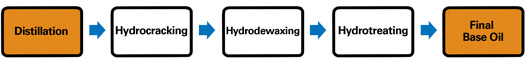
After the distillation process, the compounds need to be refined for their intended purpose. This step in the process is done to reduce the tendency of the base oil to age (oxidize) in service and also to improve the viscosity/temperature characteristics. There are two ways this can be done. The first involves a separation process where there are two products being made: a desired lube product and undesirable byproducts. The second way, which is quickly becoming the favored of the two, is a conversion process. This process involves converting undesirable molecular structures into desirable structures with the use of hydrogen, heat and pressure.

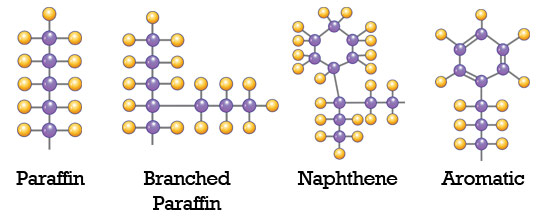
Common Mineral Oil Molecules
There are slight differences in the characteristics of the finished base oil produced by these two processes. The main difference lies in the aromatic content. The conversion process can reduce the aromatic content to around 0.5 percent, while the extraction process lingers around 15 to 20 percent. This aromatic content has the following effects:
It would appear that the conversion process produces a better quality product, but there is always a trade-off. The cost of refining oil using the conversion process is somewhat higher than the extraction process. This extra cost incurred by the refiner is eventually passed on to the customer. However, in this case, the customer typically gets what he pays for - a higher quality base oil at a higher initial price.
About the AuthorJeremy Wright
The petroleum that flows from a well in the form of crude oil comes in many varieties and types, ranging from light-colored oils containing mostly small hydrocarbon molecular chains to black, nearly solid asphalt-like large hydrocarbon chains. These crude oils are very complex mixtures containing a plethora of different compounds made of hydrogen and carbon. These compounds (known as hydrocarbons) can range in size from methane (containing one carbon and four hydrogen atoms) to massive structures with 60 or more carbon atoms. This molecular size distribution can be used to our advantage.
The Importance of Refineries
Most lubricating oils come from petroleum or crude oil. In order to get a lubricating oil from a crude oil, the crude oil must be sent through a refinery. The refinery takes from the crude oil a lot of molecules of various sizes and structures that can be used for different things. For example, gasoline, diesel and kerosene are all derived from crude oil. Lubricating oil relates to hydrocarbon molecules of a particular size (in the range from 26 to 40 carbons). Fairly large and heavy molecules are needed to work as lubricating oils. The molecules that are used with gasoline and kerosene are smaller and have fewer carbons in the structure of the molecule. The refinery puts these molecules in little silos based on size and weight, and removes impurities, enabling each of the products from the crude oil to be utilized.| 93% | of lubrication professionals would purchase a lubricant with a high-quality base oil at a higher initial price instead of a lubricant with a low-quality base oil at a lower initial price, according to a recent survey at machinerylubrication.com |
Those compounds with 26 to 40 carbon atoms are a tribologist’s main concern. This is the material used for the creation of lubricating oil. At the bottom of the column, the heaviest and largest of the hydrocarbons (40-plus carbon atoms) are taken and used in asphaltic-based products.
After the distillation process, the compounds need to be refined for their intended purpose. This step in the process is done to reduce the tendency of the base oil to age (oxidize) in service and also to improve the viscosity/temperature characteristics. There are two ways this can be done. The first involves a separation process where there are two products being made: a desired lube product and undesirable byproducts. The second way, which is quickly becoming the favored of the two, is a conversion process. This process involves converting undesirable molecular structures into desirable structures with the use of hydrogen, heat and pressure.
Extraction Process
The following is a simplified description of the extraction process:Deasphalting
Propane deasphalting takes the residuum from the very bottom of the column (the heaviest, largest molecules) and separates them into two products: tar and compounds that are similar to the lube distillates but have a higher boiling point. This material is called deasphalted oil, and it will be refined in the same manner as the lube distillates.Solvent Extraction
Solvent extraction is the term used for the removal of most of the aromatics and undesirable constituents of oil distillates by liquid extraction. Commonly used solvents contain phenol, furfural and sulphur dioxide. The resulting base stocks are raffinates (referred to as neutral oils) and an extract that is rich in aromatic content, which is highly sought after as a process oil or fuel oil.Dewaxing
After solvent extraction, the raffinates are dewaxed to improve low-temperature fluidity. This process again produces two products: a byproduct wax that is almost completely paraffinic and a dewaxed oil that contains paraffins, naphthenes and some aromatics. This dewaxed oil becomes the base stock for many lubricants, but there is one more process that can be done to make a premium product.Hydrofinishing
Hydrofinishing changes the polar compounds in the oil by a chemical reaction involving hydrogen. After this process, an observer would notice a lighter-colored product and an improved chemical stability. The final quality of the base oil is determined by the severity of the application of temperature and pressure in the hydrofining process.Conversion Process
The following is a simplified description of the conversion process:Hydrocracking
In this refining process, the distillates are subjected to a chemical reaction with hydrogen in the presence of a catalyst at high temperatures and pressures (420 degrees C and 3,000 psi). The aromatic and naphthene rings are broken, opened and joined using hydrogen to form an isoparaffin structure. The reaction with hydrogen will also aid in the removal of water, ammonia and hydrogen sulfide.Hydrodewaxing
During hydrodewaxing, much like hydrocracking, a hydrogenation unit is used to deploy a catalyst that is specific to conveying waxy normal paraffins to more desirable isoparaffin structures.Common Mineral Oil Molecules
Hydrotreating
Because the previous two processes involve breaking chemical bonds between two carbon atoms, it is necessary to introduce the saturation of any unsaturated molecules. This is easily done by introducing more hydrogen. These saturated molecules are more stable and will be able to resist the oxidation process better than the unsaturated variety.There are slight differences in the characteristics of the finished base oil produced by these two processes. The main difference lies in the aromatic content. The conversion process can reduce the aromatic content to around 0.5 percent, while the extraction process lingers around 15 to 20 percent. This aromatic content has the following effects:
It would appear that the conversion process produces a better quality product, but there is always a trade-off. The cost of refining oil using the conversion process is somewhat higher than the extraction process. This extra cost incurred by the refiner is eventually passed on to the customer. However, in this case, the customer typically gets what he pays for - a higher quality base oil at a higher initial price.
About the AuthorJeremy Wright
Jeremy Wright is a Senior Technical Consultant for Noria Corporation. Hire Jeremy to develop procedures for your lubrication program or to train your team on machinery lubrication best practices. ... Read More
Subscribe to:
Posts (Atom)