Showing posts with label Failure Mechanism. Show all posts

Thursday, 27 October 2016

Lubrication FMEA: The Big Picture

Article extract from ReliabilityWeb:
http://reliabilityweb.com/articles/entry/lubrication_fmea_the_big_picture/

The global failure modes are:
  • Obsolescence (10%)
  • Breakage (10%)
  • Surface degradation (80%)

The surface degradation causes are:
  • Corrosion - Why we paint and use protective coatings
  • Wear - Why we lubricate
  • Adhesive wear
  • Abrasive wear
  • Surface fatigue
  • Corrosive wear
Obsolescence at 10 percent appears to be growing with rapidly changing technology and increasing government regulations. Do you remember the U.S. government's Cash for Clunkers program? If you operate a coal fired power plant, can you see obsolescence on the horizon?

Breakage, also at 10 percent, is for the design engineers to use FMEA to determine how to handle today's increasing power densities and lighter weights while improving reliability in future process systems and equipment.

Surface degradation at 80 percent is further divided into wear at 65 percent and corrosion at 15 percent. With respect to lubrication, corrosion can be eliminated at this level because paint and protective coatings or stainless steel and other corrosion resistant alloys are used to protect equipment surfaces against environmental damage.

By eliminating 35 percent of the global failure modes, a Tribologist or lubrication engineer can focus on wear when using FMEA. If you don't have a lubrication engineer on your FMEA team, get one! Many organizations do not have an engineer with any formal training in lubrication or tribology - the study and application of the principles of friction, lubrication and wear.
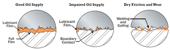
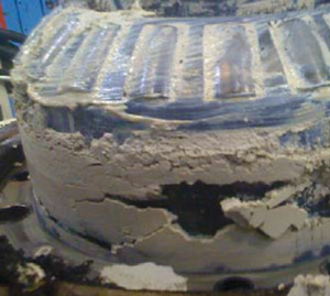
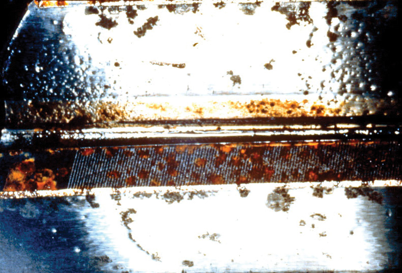

Adhesive Wear

Adhesive wear is a direct result of metal to metal contact. Surface asperities contacting under load while sliding will generate heat, friction and wear due to insufficient or loss of the lubricating film. The range of adhesive wear can be as low as running-in wear with a poorly specified break-in oil up to catastrophic damage with surfaces welded together due to total loss of lubrication.

The most important physical property of a lubricating fluid is viscosity. Viscosity measures a fluid's resistance to flow as it relates to load, temperature and speed. Viscosity determines the ability of the lubricant to enter the contact zone of the moving surfaces and remain in the contact zone under the applied load for the necessary time to prevent metal to metal contact.

Today's equipment design engineers now see the lubricant as an integral component to improve reliability. That is why it is important to read the original equipment manufacturer's manual and review the recommended oils and greases. However, when an existing process or machine is being applied in a new way, any change to the operating load, temperature, or speed must be analyzed to maintain the proper oil film.
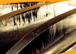
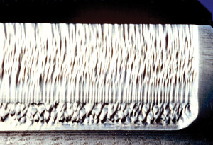

Abrasive Wear

While the saying, "cleanliness is next to godliness," does not appear verbatim in the Bible, it certainly needs to be a commandment for proper lubrication practices. Abrasive wear is caused by suspended hard particles in lubricants. These particles are a combination of wear particles generated by adhesive wear, dirt and other abrasive particles from the process or environment and, in some cases, from the degradation of the lubricant itself. Abrasive wear is why we use filtration and seals.

Never assume a new hydraulic system or piece of machinery is clean and never assume a new lubricant is clean. New machinery and systems must be flushed to remove contaminants that entered during manufacturing and assembly. If you want clean new lubricants, then you must specify the International Organization for Standardization's (ISO) cleanliness requirements for new lubricants and even then, use filtration to transfer the new lube from its container into the reservoir or sump.

Using dirty lubricants affects the entire system or machine because abrasive particles circulate throughout until they are filtered or settle in the reservoir.
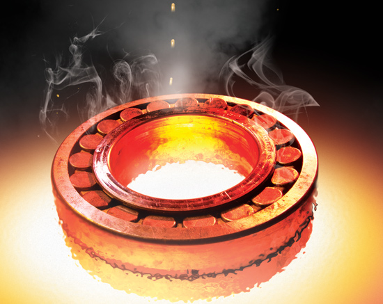
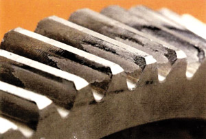
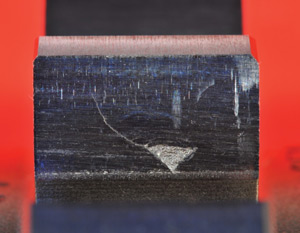

Surface Fatigue

Machinery components do not last forever; they have a designed life for their useful purposes. Premature surface fatigue is usually the result of over-speed or overload of the equipment, especially in the case of bearings and gear surfaces. Even in a perfectly lubricated bearing, if you double the speed, bearing life is reduced by 50 percent and if you double the load, the life is reduced by 87.5 percent.

We are a nation of tinkers and profit-driven to increase system production by making things faster (speed) or doing more work (load) in the same amount of time. By our own actions, surface fatigue has a dotted line impact on why equipment breaks.

Surface fatigue is extremely difficult to detect in operating systems because it is easily masked by catastrophic adhesive wear or catastrophic abrasive wear caused by large chunk spalling. Detection in operating equipment is difficult and typically requires partial disassembly and bore scoping by a trained technician, or direct reading ferrographic analysis of wear particles. In many cases, surface fatigue is only confirmed by complete machine disassembly and inspection of the failed component using magnetic, X-ray, ultrasonic, or scanning electron microscope devices.
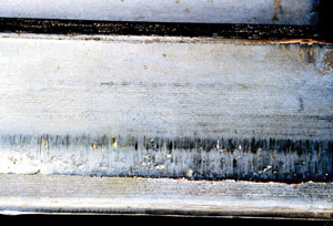

Corrosive Wear

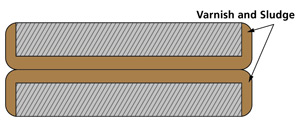
Over time, oxidation causes lubricants to become acidic. Acidic lubricants are responsible for most surface corrosion. This can be measured by the increase in the total acid number (TAN) of the used oil compared to the new lubricant's referenced TAN. In most cases, if the used oil TAN number is 2.5 higher than the new oil's referenced TAN, then the used oil is sufficiently acidic to cause surface corrosion. Oxidation reactions with the lubricant also cause internal deposits of gums, varnish and sludge. Surface corrosion caused by additive reaction is rare. It is generally found in additive reactions with copper or silver surfaces. This is easily detected using elemental oil analysis.

In conclusion, by adding the above risk priority numbers (RPNs) in Figures 2-5, the sum is 65.005% representing the global percentage of equipment failure modes caused by surface degradation. The best way to reduce this global failure mode percentage in your processes and equipment is to improve your lubrication program.

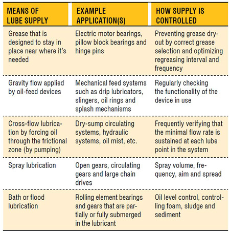
The lubrication program should emphasize the selection of lubricants that must be application driven based on the load, environment, temperature and speed of the process. The lubrication program also must ensure the five basic rights of machinery, which are the right lubricant of the right quality delivered in the right place at the right time in the right amount. Formal lubrication training is needed to establish a truly effective lubrication program. Most organizations require a cultural change in the way they view lubrication fundamentals.


John Cummins is vice president of product technology at Hydrotex®, a manufacturer and distributor of high performance lubricant and fuel improver solutions. He is the Dean of Hydrotex Lubrication University, a comprehensive lubrication education program for the sales field and Hydrotex customers. He is a certified lubrication specialist by the Society of Tribologists and Lubrication Engineers (STLE). www.hydrotexlube.com

Wednesday, 3 August 2016

Keys for Testing Transformer Oils

Article extract from ReliaPlant newsletter:

Transformer oils serve several functions. They provide dielectric strength, protect the solid insulation and facilitate heat transfer. Perhaps most importantly, they also offer a way to determine if a problem exists when looking inside the transformer.

34%of lubrication professionals perform transformer oil analysis twice a year, based on a recent poll from machinerylubrication.com

While several different dielectric fluids are used in transformers today, by far the most common are mineral oils. Of these, the majority are of naphthenic base stocks. Generally speaking, naphthenics have a lower natural pour point and a lower viscosity index (VI). Obviously, the lower pour point is beneficial for the lower temperatures found in some climates and during the winter months.

Due to the lower viscosity index of naphthenic base oils, a rise in temperature has a greater effect on the viscosity of the oil. As the temperature increases, the viscosity decreases and the heat-transfer rate is improved. For oils of equal viscosity at 40 degrees C, the heat-transfer coefficient can be 8 to 11 percent greater for a naphthenic oil than for a paraffinic oil.


As a mineral oil, the transformer oil’s usable life can be optimized if it is kept clean, cool and dry. Upon receipt and prior to use, these oils should be tested for particulate and water contamination among others using the following tests: acid number (ASTM D664), dielectric breakdown voltage (ASTM D877), liquid power factor (ASTM D924-08), interfacial tension (ASTM D971), specific resistance (ASTM D1169), corrosive sulfur (ASTM D1275), visual examination (ASTM D1524), Karl Fischer water (ASTM D1533), dielectric breakdown voltage (ASTM D1816), gassing tendency (ASTM D2300), oxidation stability (ASTM D2440), gas chromatography (D3612), oxidation inhibitor (ASTM D4768 or D2668) and particle count (ASTM D6786). These tests will determine whether you are receiving clean oil and will establish a baseline of the oil properties that should be tested periodically. Although there are a number of tests to which the oils can be subjected, some are quite expensive, so they may be best used as diagnostic tests if an issue is indicated in more routine testing.

The recommended frequency of transformer oil analysis is dependent on both the voltage and power. The chart on the left can serve as a guideline but does not take into consideration the transformer’s operating environment.

If results from a periodic test raise a red flag, the frequency should be increased. Even if the cost of the tests is high, the expense should be compared with the cost of replacing a transformer and the downtime associated with the loss of a transformer.


The most common in-service tests are the dielectric breakdown voltage (ASTM D877), interfacial tension (ASTM D971), acid number (ASTM D664), oxidation inhibitor (ASTM D4768 or D2668), Karl Fischer water (ASTM D1533), visual examination (ASTM D1524), and dissolved gas analysis (ASTM D3612). The sampling for these tests is critical. Be sure to follow ASTM D923-07. Any deviation from this procedure may result in test data that does not offer an accurate picture of the condition of the oil or the internal components.

It is important to differentiate between normal and excessive gassing rates. These will vary based on the transformer design, insulation material and loading. It is recommended that laboratories use key gas analysis (KGA) supplemented by the Dornenburg and Rogers ratios in analyzing dissolved gas analysis (DGA) results. DGA measures the oil for methane, acetylene, ethylene, hydrogen, ethane and carbon monoxide. It can also provide an indication of arcing, corona, overheating oil and overheating cellulose.


Other tests that can be performed measure inorganic chlorides and sulfates (ASTM D878) and specific gravity (ASTM D1298). Some of these tests will be conducted by the blender or supplier. These tests will establish a baseline for comparison in future analysis.

Keep in mind that it is not uncommon for transformer oils to be in use for 30 years or more, so a little expense on the front end can lead to huge returns in the future.


About the Author

Wednesday, 29 June 2016

Preventing Micropitting and Surface Fatigue

Article extract from Machinery Lubrication newsletter:
http://www.machinerylubrication.com/Read/29276/micropitting-surface-fatigue

Many gears can be affected by a phenomenon known as micropitting. This condition is seen when microscopic cracks form on gears and through time and stress result in microscopic pits. These pits grow larger and eventually break away. This can even be a primary failure mode for gears.

Micropitting generally occurs under elastohydrodynamic lubrication (EHL). When the oil film thickness under EHL becomes too thin at the gear pitchline, surface asperities will begin to come into contact. When these asperities contact each other on opposing surfaces and under high load, they cause elastic or plastic deformation, which leads to micropitting.

81%of lubrication professionals have seen the effects of micropitting or surface fatigue in the gears at their plant, based on a recent survey at machinerylubrication.com

Surface fatigue is very similar. Under elastohydrodynamic lubrication, surface fatigue often results from denting on a surface due to hard or soft particles. The dents in the surface create what are known as berms. Over time and with repeated high loading, pits develop where the surface breaks apart. With continued high loading, the pits become larger.

The Effects

Surface fatigue and micropitting are influenced by the particular lubricant being used, including its base oil, additives, viscosity selection and particle contamination. While micropitting or surface fatigue can occur with synthetic or mineral oil lubricants, synthetics can provide better protection at higher temperatures than mineral oils with the same viscosity grade and additive package. This is due to the fact that synthetics can have a higher viscosity index. In other words, the viscosity of synthetics may change less with an increase in temperature.

Although extreme pressure (EP) additives are often necessary, in certain cases they can be very chemically aggressive to surfaces and cause micropitting. These types of additives also become more active with higher temperatures. Some researchers claim oils that do not have EP additives will exhibit a maximum resistance to micropitting. An oil’s ability to protect against micropitting can be determined using the FZG FVA 54 test.

High-viscosity oils also have a greater resistance to micropitting because of their thicker EHL films. However, going to a higher viscosity is not always the best option because it can cause higher operating temperatures, energy loss and/or an increased rate of oil oxidation.

High Risk Contacts

Anywhere rolling contact occurs in machinery there is potential for micropitting and surface fatigue. This would include rolling-element bearings (along the base of the raceway). Gears also have rolling contact, which usually occurs around the pitchline. Cams and rollers are other examples of where you can see rolling contact and thus possible surface fatigue and micropitting.

Particles that are much larger than the EHL film thickness can become entrained between surfaces due to a rolling action. Once these particles are in the contact area, they are subjected to massive amounts of contact pressure. Particles with lower compressive strength under this contact pressure can break into smaller pieces, with some embedding in the surfaces and others passing through the contact zone. Harder particles that are larger than the EHL film thickness can pass through the contact zone by denting the softer surface. As mentioned previously, these dents create berms (shoulders) and, over time with more contact pressure, can dislodge from the surface.

Controlling Micropitting and Surface Fatigue

Selecting the right viscosity is key in reducing micropitting and surface fatigue. Higher loads will require higher viscosity, while lower loads allow for lower viscosities. Speed can also have an effect on micropitting and surface fatigue. At lower speeds, the film thickness will decrease. Likewise, at higher speeds, the film thickness can increase. This is another factor to consider in selecting the correct viscosity for your application. The operating temperature also plays a role in micropitting and surface fatigue. As the temperature increases at the contact area, the oil’s viscosity becomes lower and film thickness decreases. As the temperature increases, a lubricant with too low of a viscosity will become thinner and not provide adequate protection, leading to an increased rate of micropitting and surface fatigue. If an EP oil is used, the EP additives become more reactive at higher temperatures and can offer protection from adhesive wear.

Of course, too high of a viscosity can also generate excessive heat. This heat that is caused by too high of a viscosity will lead to accelerated oxidation. If oil analysis is not used to determine the remaining useful life and trigger the need for an oil change, the oil will break down and not provide sufficient protection.

Thursday, 3 July 2014

The Hidden Dangers of Lubricant Starvation

Article extract from Reliable plant newsletter:
http://www.machinerylubrication.com/Read/29040/lubricant-starvation-dangers   

    
For those who strive for lubrication-enabled reliability (LER), more than 95 percent of the opportunity comes from paying close attention to the “Big Four.” These are critical attributes to the optimum reference state (ORS) needed to achieve lubrication excellence. The “Big Four” individually and collectively influence the state of lubrication, and are largely controllable by machinery maintainers. They are well-known but frequently not well-achieved. The “Big Four” are:
  1. Correct lubricant selection
  2. Stabilized lubricant health
  3. Contamination control
  4. Adequate and sustained lubricant level/supply
The first three of the “Big Four” have benefited from considerable industry attention, especially in recent years. Conversely, the last one has gone relatively unnoticed yet is no less important. Therefore, it will be the central focus of this article.
Over the past few decades, researchers and tribologists have compiled countless listings that rank the chief causes of machine failure. We’ve published many of these in Machinery Lubrication magazine. The lists ascribe the causes of abnormal machine wear to the usual suspects: contamination, overheating, misalignment, installation error, etc. There’s typically a lubrication root-cause category that is a catch-all for one or more causes that can’t be easily specified or named. I’ve seen terms used like “inadequate lubrication” and “wrong lubrication.”
Understandably, it is difficult for failure investigators and analysts to trace back the exact sequence of events beginning with one or more root causes. Evidence of these causes is often destroyed in the course of failure or in a cover-up during the cleanup and repair. Having led several hundred such investigations over the years, I’ve learned that one root cause in particular is too often overlooked - lubricant starvation.
81% of lubrication professionals have seen the effects of lubricant starvation in the machines at their plant, according to a recent survey at machinerylubrication.com
Although most everyone knows about this in principle and realizes the common sense of adequate lubricant supply, it is frequently ignored because many typical forms of lubricant starvation are largely hidden from view. For instance, who notices the quasi-dry friction that accelerates wear each time you start an automobile engine? This is a form of lubricant starvation. It’s not a sudden-death failure, but it is a precipitous wear event nonetheless. Each time controllable wear goes uncontrolled, an opportunity is lost to prolong service life and increase reliability.

The Nature of Lubricant Starvation

Machines don’t just need some lubricant or any lubricant. Rather, they need a sustained and adequate supply of the right lubricant. Adequate doesn’t just mean dampness or the nearby presence of lubricant. What’s defined as adequate varies somewhat from machine to machine but is critical nonetheless. High-speed equipment running at full hydrodynamic film has the greatest lubricant appetite and is also the most punished when starved. Machines running at low speeds and loads are more forgiving when lube supply is restricted. Even these machines can fail suddenly when severe starvation occurs.
The table below illustrates how lubricants reach frictional surfaces in numerous ways.
There are six primary functions of a lubricating oil. These are friction control, wear control, temperature control, corrosion control, contamination control and transmittance of force and motion (hydraulics). Each of these functions is adversely influenced by starvation conditions. The worst would be friction, wear and temperature control. Even partial starvation intensifies the formation of frictional heat. It also slows the transport of that heat out of the zone. This is a compounding, self-propagating condition that results in collapsed oil films, galling, adhesive wear and abrasion (Figure 1).

Figure 1. Starvation Illustrated
In the case of grease, starvation-induced heating (from friction) of the load zone accelerates grease dry-out, which escalates starvation further. Heat rapidly drains oil out of the grease thickener, causing volatilization and base oil oxidation, all of which contributes to hardening and greater starvation.
Lubricating oil needs reinforcement, which is lost when flow becomes restricted or static. Flow brings in bulk viscosity for hydrodynamic lift. In fact, lack of adequate lubricant supply is functionally equivalent to inadequate viscosity from the standpoint of film strength.

4 Keys to Solving Starvation Problems Using Proactive Maintenance

  1. Identify the required lube supply or level to optimize reliability.
  2. Establish and deploy a means to sustain the optimized supply or level.
  3. Establish a monitoring program to verify the optimized supply or level is consistently achieved.
  4. Rapidly remedy non-compliant lube supply or level problems.
Oil flow also refreshes critical additives to the working surfaces. This reserve additive supply includes anti-wear additives, friction modifiers, corrosion inhibitors and others. Lubricant starvation produces elevated heat, which rapidly depletes additives.
Next, we know that wear particles are also self-propagating. Particles make more wear particles by three-body abrasion, surface fatigue and so on. Impaired oil flow inhibits the purging of these particles from the frictional zones. The result is an accelerated wear condition.
Finally, moving oil serves as a heat exchanger by displacing localized heat generated in load zones outward to the walls of the machine, oil reservoir or cooler. The amount of heat transfer is a function of the flow rate. Starvation impairs flow and heat transfer. This puts increasing thermal stress on the oil and the machine.

Common Signs of Starvation

When you’re encountering chronic machine reliability problems, think through the “Big Four” and don’t forget about No. 4. It may not be the type of oil, the age of the oil or even the contamination in the oil, but rather the quantity of oil. How can you know? The chart on page 8 reveals some common signs of lubricant starvation.

Lubricant Starvation Examples by Machine Type

Lubricant starvation can happen in a number of ways. Most are controllable, but a few are not. The following abbreviated list identifies how lubricant starvation occurs in common machines.

Starved Engines

  • Dry Starts - Oil drains out down to the oil pan when the engine is turned off. On restart, frictional zones (turbo bearings, shaft bearings, valve deck, etc.) are momentarily starved of lubrication (Figure 2).

    Figure 2. Dry Engine Starts
  • Cold Starts - Cold wintertime conditions slow the movement of oil in the engine during start-up. This can induce air in the flow line due to cold-temperature suction-line conditions.
  • Low Oil Pressure - This can result from numerous causes, including worn bearings, pump wear, sludge and extreme cold. Oil pressure is the motive force that sends oil to the zones requiring lubrication.
  • Dribbling Injectors - Fuel injector problems can wash oil off cylinder walls and impair lubrication between the piston/rings and the cylinder wall.

    Common Signs of Lubricant Starvation
  • Clogged Spray Nozzles and Orifices - Nozzles and orifices direct oil sprays to cylinder walls, valves and other moving components. Sludge and contaminants are able to restrict oil flow.

Starved Journal and Tilting-Pad Thrust Bearings

  • Oil Groove Problems - Grooves and ports channel oil to the bearing load zones. Grooves become clogged with debris or sludge, restricting oil flow.
  • Restricted Oil Supply - Pumping and oil-lifting devices can become mechanically faulty. This also may be due to low oil levels, high viscosity, aeration/foam and cold temperatures.
  • Sludge Dam on Bearing Leading Edge - Sludge can build up on the bearing’s leading edge and restrict the oil supply.

Wet-Sump Bearing and Gearbox Starvation

  • Oil Level - Many wet-sump applications require critical control of the oil level (Figure 3).

    Figure 3. Common Splash Gear Drive
  • High Viscosity - Many oil-feed mechanisms (oil rings, slingers, splash feeders, etc.) are hampered by viscosity that is too high (wrong oil, cold oil, etc.). Gears can channel through thick, cold oil, interfering with splash and other feed devices.
  • Aeration and Foam - Air contamination dampens oil movement and impairs the performance of oil-feed devices (Figure 4).

    Figure 4. How Aeration Retards Oil Supply
  • Non-horizontal Shafts - This can cause drag on oil rings and may interfere with slinger/flinger feed mechanisms.
  • Bottom Sediment and Water (BS&W) - Sump BS&W displaces the oil level. On vertical shafts, the bottom bearing can become completely submerged in BS&W.
  • Defective Constant-Level Oilers - This may be due to plugged connecting pipe nipples, mounting errors (tilted, cocked, mounted on wrong side, etc.), wrong level setting, empty reservoir, etc. (Figure 5).

    Figure 5. Mounting Errors of Constant-Level Oilers
  • Defective Level Gauge Markings - Level gauges should be accurately calibrated to the correct oil level.
  • Level Gauge Mounting and Viewing Issues - These may be hard to see, goosenecks, fouled gauge glass, gauge vent problems, etc. (Figure 6).

    Figure 6. What is wrong with this picture?

Starved Dry-Sump Circulating Systems

  • Restricted Oil Returns - Plugged or partially plugged oil returns will redirect oil flow away from the bearing or gearbox being lubricated. Sometimes called drip-and-burn lubrication, the condition is usually caused by sludge buildup or air-lock conditions in the gravity drain lines returning to the tank.
  • Worn Oil Pump - When oil pumps wear, they lose volumetric efficiency (flow decay results).
  • Restricted Pump Suction Line - Strainers and pickup tubes can become plugged or restricted. This can aerate the fluid, cause cavitation and lead to loss of prime.
  • Clogged/Restricted Oil Ways and Nozzles - Oil-feed restrictions due to sludge, varnish and jammed particles can starve bearings and gears (Figure 7).

    Figure 7. Plugged Oil Flow
  • Entrained Air and Foam - Oil pumps and flow meters perform poorly (or not at all) when sumps become contaminated with air (Figure 4).
  • Lack of Flow Measurement - Components sensitive to oil supply require constant oil flow measurement.
  • Defective or Miscalibrated Flow Meters - Flow meters, depending on the type and application, can present a range of problems regarding calibration.
  • Low Oil Pressure - Oil follows the path of least resistance. Line breaks and open returns starve oil from higher resistance flow paths and the machine components they serve.

Starved Spray-Lubed Chains and Open Gears

  • Defective Auto-lube Settings - This relates to correctly setting the lube volume and frequency.
  • Defective Spray Targets/Pattern - The oil spray needs to fully wet the target location. Spray nozzles can lose aim and become clogged (Figure 8).

    Figure 8. Correct Lubricant Spray Patterns
    on Open-Gear Tooth Flanks
  • Gummed Chain Joints - Many chains become heavily gummed, which prevents oil from penetrating the pin/bushing interface.

Starvation from Grease Single- and Multi-Point Auto Lubrication

  • Wrong Regrease Settings - Regreasing settings should enable adequate grease replenishment at each lube point.
  • Cake-Lock - This occurs when grease is being pumped. Under certain conditions, the grease thickener movement is restricted. Oil flows, but the thickener is log-jammed in a line or component passage (Figure 9).

    Figure 9. Cake-Lock
    Grease Starvation
  • Defective Injector Flow - This is due to wrong injector settings or restricted injector displacement.
  • Restricted Line Flow - Exceedingly long lines, narrow lines, numerous bends, ambient heat or cold, etc., can lead to partial or complete blockage of grease flow.
  • Single-point Lubricator Issues - These include malfunctioning lubricators from various causes.

Starvation from Manual Lubrication Issues

  • Grease Gun Lubrication - This may include an inaccurate volume calibration, a faulty grease gun mechanism, the wrong relube frequency, an incorrect relube volume or an improper relube procedure.
  • Manual Oil Lubrication - This would include the wrong relube frequency, volume or procedure.
  • Lube Preventive Maintenance (PM) - Missed PMs may be due to scheduling, management or maintenance culture issues.

The Crux of the Problem

Lubricant starvation is an almost silent destroyer. While there are telltale signs, they generally aren’t recognized or understood. Of course, there are varying degrees of starvation. Complete starvation is sudden and blatant. However, more moderate partial starvation is what tends to go unnoticed until failure. Then, other suspect causes (the bearing, lubricant, operator, etc.) may be falsely blamed.
Precision lubrication supply is a fundamental attribute of the optimum reference state and is included in any engineering specification for lubrication excellence. It’s one of the “Big Four” and thus is overdue for significant attention.

About the Author
Jim Fitch
Jim Fitch, a founder and president of Noria Corporation, has a wealth of experience in lubrication, oil analysis, and machinery failure investigations. He has advised hundreds of companies on ... 

Friday, 8 March 2013

Analyzing Gear Failure

Article from Reliable Plant Newsletter
http://www.machinerylubrication.com/Read/28978/analyzing-gear-failures


Best Practices for Analyzing Gear Failures


With all the different gearbox failure modes, it’s important to be aware of the various tests that can be used to develop and confirm a hypothesis for the probable cause of failure. Lubricant samples can provide immediate means to detect contamination or other adverse changes to the lubricant. These samples can be sent to a laboratory for further analyses. There are also a number of tests that can be performed on-site and at a low cost to check for lubricant contamination or oxidation.

Appearance Test

The simplest test is visual appearance. Often this test will disclose problems such as gross contamination or oxidation. Look at the lubricant in a clean, clear bottle. A tall, narrow vessel is best. Compare the sample to a sample of new, unused lubricant. The oil should look clear and bright. If the sample looks hazy or cloudy, or has a milky appearance, there might be water present. The color should be similar to the new oil sample. A darkened color might indicate oxidation or contamination with fine wear particles. Tilt the bottle and observe whether the used oil appears more or less viscous than the new oil. A change in viscosity might indicate oxidation or contamination. Look for sediment at the bottom of the bottle. If any is present, run a sedimentation test.

Sedimentation Test

If any sediment is visible during the appearance test, a simple test for contamination can be performed on-site. Place a sample of oil in a clean, white cup made from a non-porous material that is compatible with the lubricant. Cover and allow it to stand for two days. Carefully pour off all but a few milliliters of oil. If any particles are visible at the bottom of the cup, contaminants are present. Resolution of the unaided eye is about 40 microns. If the particles respond to a magnet under the cup, iron or magnetite wear fragments are present. If they don’t respond to the magnet and feel gritty between the fingers, they are probably sand. If another liquid phase is visible or the oil appears milky, water is likely present.

This image shows how severe misalignment
can limit the contact area and cause macropitting.

Odor Test

Carefully sniff the oil sample. Compare the smell of the used oil sample with that of new oil. The used sample should smell the same as new oil. Oils that have oxidized have a “burnt” odor or smell acrid, sour or pungent.

Crackle Test

If the presence of water is suspected in an oil sample, a simple on-site test can be performed. Place a small drop of oil onto a hot plate at 135 degrees C. If the sample bubbles, water is above 0.05 percent. If the sample bubbles and crackles, water is above 0.1 percent. When carrying out the crackle test, the inspector’s health and safety must be taken into consideration by wearing eye protection, for example.

Why Take Oil Samples from a Failed Gearbox?

Laboratory analysis of oil samples from a failed gearbox might answer the following questions:
  • Does the oil meet the original equipment manufacturer (OEM) specification?
  • Was the oil contaminated?
  • Was the oil degraded?
  • Does the oil contain evidence useful for finding the root cause of failure?
  • Is the oil representative of the service oil?
45%of lubrication professionals consider the appearance test to be the most effective on-site test to check for lubricant contamination or oxidation, according to a recent survey at machinerylubrication.com

Does the Oil Meet the OEM’s Specification?

Sometimes a gearbox fails because the wrong oil was used. To prove whether the oil meets the OEM’s specification, the following laboratory tests should be performed on used oil samples and compared to laboratory test results from samples of fresh, unused oil that conforms to the OEM’s specification:
  • Viscosity at 40 degrees C and 100 degrees C (ASTM D445)
  • Spectrometric analysis to determine elements in the oil (ASTM D5185 or D6595)
  • Acid number (ASTM D664 or D974)
  • Infrared spectroscopy to determine additive content (ASTM D7412, etc.)

Micropitting often will have a pattern that indicates misalignment.


A lubricant with inadequate anti-scuff additives caused scuffing on this spiral bevel pinion.

Was the Oil Contaminated?

The fatigue life of gears and bearings is adversely affected by water. For example, as little as 50 ppm of water reduces rolling bearing fatigue life by 75 percent. Therefore, the Karl Fischer titration method (ASTM D6304) should be used to determine the water content. Other laboratory tests such as viscosity, spectrometric analysis and infrared analysis can help determine if other fluids such as the wrong oil, flushing oil or coolant contaminated the service oil. Spectrometric analysis might disclose contamination via environmental dust by showing high concentrations of silicon and aluminum.

A lubricant contaminated with water produced corrosion on this helical gear.

Was the Oil Degraded?

The oil might lose its ability to lubricate if its viscosity changes significantly or if it is oxidized. The manufacturing tolerance on viscosity is plus or minus 10 percent. Therefore, ISO VG 320 oil should have a viscosity that falls within the range of 288 to 352 centistokes at 40 degrees C.
There are many possible causes for an increase or decrease in viscosity. For example, some oils have additives known as viscosity-index (VI) improvers that might not be shear stable. With time in service, these oils lose viscosity because the VI improvers shear down.
In addition, overheating might cause oxidation. Contamination by water and wear debris accelerates oxidation. The following symptoms are indicative of oxidation:
  • A foul odor (sour, pungent or acrid smell)
  • A dark color
  • An increase in viscosity
  • An increase in the acid number
  • A shift in the infrared spectrum

Does the Oil Contain Evidence for Finding the Root Cause of Failure?

Wear debris in the oil may help indicate failure modes that occurred in the gearbox and reveal contaminants that contributed to the failure. Spectrometric analysis can uncover contamination via environmental dust by showing high concentrations of silicon and aluminum. These results might explain abrasion on gear teeth and bearing surfaces. Depletion of anti-scuff additives may confirm a scuffing failure, and excessive water concentration might explain corrosion.
Other test methods used to monitor abnormal wear of gearboxes include ferrous density, particle counting (ASTM D7647) and analytical ferrography (ASTM D7690).
Direct reading (DR) ferrography is a ferrous density test that measures the amount of ferrous wear debris in an oil sample. The results of DR ferrography are generally given in terms of DL for particles greater than 5 microns and DS for particles less than 5 microns in size.
Analytical ferrography allows wear particles to be observed by the analyst via microscopic analysis. In this evaluation, active machine wear as well as multiple different modes of wear can be determined. This method has an outstanding sensitivity for larger particles.
Particle counting in industrial gearboxes tells the same story as particle counting in a hydraulic system or pump application - that of cleanliness. When establishing an oil analysis program that is proactive in controlling contamination, particle counting is a vital component to the routine test slate.

This is an example of point-surface-origin
(PSO) macropitting caused by tip-to-root interference.

In this example, abrasion and scuffing
have been caused by tip-to-root interference.

Is the Oil Representative of the Service Oil?

If the oil appears very clean, it might have been changed after the failure occurred. Therefore, check maintenance records and interview maintenance personnel to determine whether the oil is representative of the oil that was in service when the failure took place.

Sampling Procedures during an Oil Drain

Always use clean, lubricant-compatible plastic or glass sample bottles and caps, and keep all sampling equipment thoroughly clean. Prior to sampling, fill out the label and attach it to the sample bottle. Be sure to record the sample point and the date.
The equipment needed for proper draining and sampling includes:
  • Clean containers for holding the drain oil
  • A wire-mesh screen
  • Four or more clean laboratory bottles (clear plastic) for taking samples
  • A large bottle for capturing excess water

First Oil Sample

Drain the oil through the screen to capture any large wear debris or fracture fragments that might be entrained in the drain oil. Take the first oil sample at the start of the drain. Be prepared to capture any free water that may have settled in the gearbox. If there is a large quantity of water, fill a sample bottle and then capture the remaining water in the large bottle. Once the water stops flowing, take a sample of the oil.


A lubricant contaminated by sand
resulted in abrasion on this spur pinion.

Second Oil Sample

Take the second oil sample near the middle of the drain. Estimate the oil level in the gearbox from the sight gauge or from direct measurements. This sample will be used to determine bulk oil properties that are more representative of the in-service oil properties.

Third Oil Sample

Take the third oil sample near the end of the drain. This sample might capture less dense contaminant fluids.
When all the calculations and tests are completed, form one or more hypotheses for the probable cause of failure and then determine if the evidence supports or disproves the hypotheses. While similar procedures apply to any failure analysis, the specific approach can vary depending on the nature of the failure and time constraints.
So whether you perform tests on-site or send oil samples to a laboratory for further analysis, be sure to select the appropriate test to help you correctly determine the probable cause of a failed gearbox.

About the Author

Robert Errichello is a gear consultant with GearTech. Contact him at geartech@mt.net.

Wednesday, 16 January 2013

Managing the depth of RCM

RCM stands for Reliability Centred Maintenance. It is a process whereby a series of questions are structurally raised to conclude a maintenance requirement. It can be as tedious as a full blown RCM where you are moving on average about 3-4 Failure Modes an hour in a RCM workshop to a quick straight forward 30-50 Failure Modes an hour in a peer review workshop.

How deep to go for the RCM analysis? There're a few things to consider when making this call.

  1. How skilled are your maintenance team in addressing the Failure Modes? There is no point going into too detail if your trades does not share the understanding and knowledge. For example, carrying out vibration analysis on an equipment without a skilled person is useless. No one will be able to interpret the data and put it to good use. Your strategy would then have to be fine tuned to fixed-time replacement on an optimized shutdown interval.
  2. How critical is the equipment? The more critical it is, the more time should be invested towards making it performing reliably.
  3. What is the current state of the maintenance strategy? Is it running reliably? If it is, are we seeing potential Failure Modes that we are not addressing? A peer review to close the gap in the strategy is sufficient in this case. If the equipment is not reliable to start with, it may require a full blown RCM from scratch.
  4. There will be times where you run into a highly critical equipment but yet the Failure Modes are highly unlikely. The facilitator or reliability engineer would have to make the call whether a full blown RCM is worthwhile or manage the risk with a peer review process to ensure all gaps in strategies are covered. This require local plant experience that none of your external consultants have. Re-emphasize, invest in your reliability team!
  5. ???


A note to reliability managers out there, if a person pitch you they can deliver RCM workshop at 15 Failure Modes an hour, be very wary about it. You get what you pay for. Quality takes time and it is inevitable in RCM! Again, your best value is through having invest in a very good reliability engineer on your side. After all, the RCM databases will still require maintenance and update in-house, unless you are ready to pay the continual work from the consultancy.

Friday, 16 November 2012

Plant Mothballing

Read an article in Reliable Plant newsletter today. Made me aware of some work involved prior to mothballing a plant. Good start to that area of practice anyway. :)

http://www.reliableplant.com/Read/28796/do-before-plant-closure

What You Should Do Before a Plant Closure

It’s happened … the announcement that a major portion of your facility is being closed for the foreseeable future. What do you do next?
  1. Accept the news that your plant is facing an impending plant shutdown. It is not necessarily a “knockout” for the plant or your career. Remember, in the often uneven battleground called the global marketplace, just about anything can happen. Be ready to get up and start fighting again.
  2. Designate responsibility to an individual for writing a list of possible scenarios. The individual should have enough clout to implement the chosen strategy, if necessary.
  3. Go to the top of the company and request that sufficient funds be made available to execute the initial shutdown and preservation strategy.
  4. Choose the right type of long-term equipment caretakers. Those selected are often security or ex-supervisory types rather than experienced operator/craftsmen with intimate knowledge of the equipment.
  5. Don’t allow critical components to be pirated (stolen for use elsewhere) if part of a larger plant.
  6. Remove all process materials. Even innocuous materials left in the unit in the long term will likely cost five times more than at the initial shutdown. The current operations people are familiar with all the hazards.
  7. Seek expert advice on equipment preservation resulting in not getting the best bang for the buck.
  8. Involve the hourly workforce in the shutdown and mothball plan. Almost unbelievably, our recent experience has been that if the decision to shut down at some future date has been made, then involving operators and mechanics can very much improve both the quality of the shutdown plan and its execution.
  9. Not only record but clearly and physically mark what has been done to preserve the item of equipment during deactivation. The reactivating crew (probably a different group of people) can easily miss that a filter, line blind, internal component, etc., has been removed or added with serious consequences at a future start-up.
In our experience, idle plants with small crews operating at a very relaxed tempo can be dangerous places. Make sure safety programs and routine audits are kept active to avoid accidents.
Just as with any critical situation, a long-term strategic approach coupled with a series of medium-term tactics and detailed plans are needed. You should also consider how long the shutdown is probably going to last (guesstimate) and whether the plant will most likely be restarted, sold as a complete unit or sold piecemeal.
Examine every item or class of equipment individually and write a specific initial storage/mothball technique plus a methodology for ongoing maintenance.
For the purposes of this article, let’s consider an item of equipment or a whole plant that might restart as early as six to nine months but could also be several years.
Unused plants and equipment that are properly prepared for shutdown and left in fairly good condition can retain much of their value. However, if a plant is left “as is” and allowed to deteriorate, as is normally the case, much of it can be fit only as scrap in just a matter of months. Engaging in a well-planned process of deactivation/mothballing can be worthwhile either way, whether it should ever be reactivated or just sold for its second-hand value at some future point.

Materials and Equipment You Will Need

Having a clear view of how the constant foes of galvanic/bio corrosion, mold, mildew, etc., can be mitigated if not defeated is essential. Although much will depend on local conditions, the wetter and colder situations are much more challenging in terms of handling humidity, while blowing dust is an issue for those in the high desert regions. For this article, we will consider a central United States or European location.
A useful analogy in developing a strategy is to compare what it takes to maintain fire. In the case of fire, there are three essential legs: heat, a fuel source and oxygen. Likewise, age-related deterioration involves a driving force (such as galvanic action), a conducting medium (electrolyte) and oxygen. The fundamental approach to stopping or slowing this age-related deterioration is to remove one or more of the three legs.
In simple terms, we aim to do the following:
  • Separate dissimilar metals.
  • Protect surfaces that could be attacked, even with a covering of only a few molecules thick.
  • Dry out or remove the conducting medium (electrolyte — air or gas). Corrosion cannot occur when parts are stored in environments where the relative humidity is held below 40 percent.
  • Remove any oxygen or sources of chemical or biological attack.
The materials we can use are:
  • Liquid protective waxes and liquid polyvinyl chloride (PVC) coating — These can be sprayed on any clean, dry surface to protect them. Wherever it is applied, PVC will form a tough, flexible, waterproof skin that will withstand the extremes of temperature, thermal shock, differential substrate movement and impingement even when sprayed on webbing to form a cocoon.
  • Volatile corrosion inhibitors (VCIs) — These generate protective vapors even at room temperatures. They come in a number of convenient forms, including time-release vaporizers, sprays, plastic bags and films, powders, oil additives and coatings. They are adsorbed onto the metallic surfaces of the equipment (just a few molecules thick), where they can prevent corrosion for up to two years. While most VCIs are environmentally friendly and create no safety hazards for employees, there are some that are suspected of being harmful. Most contain no toxic substances, such as nitrates or chromates. (Note: Volatile organic compounds should not be used in combination with a desiccant.)
  • Vapor space inhibitor (VSI) — This is an oily concentrate that can be added to lubricating oil systems (internal combustion engines, etc.) when equipment is not going to be completely filled.
  • Heat-shrinkable plastic films — These are ideal for enclosing individual machines that have been cleaned and dried and have internal desiccants added.
  • VCI-covered polythene films — These are used to wrap individual smaller components.
  • Chemical oxygen scavengers — These are frequently added to fresh water used to displace more corrosive liquid in systems that can’t be effectively cleaned or dried out.
  • Chemical inhibitors — These are added to liquids and chemicals and are designed to remove unwanted products while preferentially inhibiting their attack on the body of the container. (Antifreeze sometimes used in this process contains them.)
  • Desiccants — These include numerous substances (solids) that absorb water from gases (air) or liquids.
  • Biocides — These are used to prevent microbial growths in water and fuels such as gasoline and diesel fuel.
  • Light waxes — These are used as surface protectors for metals.
  • Sacrificial Anodes — These are used in tanks that cannot be drained of their contents.
The primary pieces of equipment are dehumidifiers. These are available in two forms: those that work on the refrigeration principle and those that use two-cycle rotary (wheel) heated desiccant absorption.

Strategies by Equipment Class

Before considering individual techniques, make a best guess of the duration and whether it is going to be an “attended monitored” lay-up or a “walk-away” lay-up. This article is simply a guide and is not intended to be totally comprehensive and detailed.

Tanks, Pressure Vessels and Pipework

It is essential that tanks, pressure vessels and pipework be left as clean and dry as possible. Insert line blinds to create manageable zones that can be slightly pressurized (0.5 psig+) using nitrogen or dry air. Include some small flow and arrange for some simple telltale mechanism to show pressure flow and the level of humidity (indicator cards). For large enclosures, use a commercial dehumidifier of an appropriate capacity. For vessels, tanks and containments that must be kept full of liquid, some form of oxygen scavenger or anti-biological growth chemical can be used (see boilers). If a pipework system contains any traps, have its internals removed and clear all strainers.

Boilers

Boilers can be laid up using either the long-term dry method or the hydrazine wet lay-up method, which involves leaving the wet side (boiler, economizer and super heater) full of feed-treated water. The feed water is dosed with 15 percent hydrazine and then pH-adjusted to raise the alkalinity to a minimum pH of 8.3. The fire side is supplied with heated air, with desiccant as a backup. Both water-side and fire-side points should have new gaskets, except for furnace hot-air entry inspection and exit points.

Pumps, Engines, Compressors and Machinery

To minimize internal corrosion, close off all vents and openings, and completely fill the casing with the manufacturer’s recommended lubricant. Alternatively, add a volatile corrosion inhibitor in the correct proportion to the lubricating oil. For large compressors, turbines, etc., first centrifuge/circulate the existing oil using a portable filtration cart through water-absorbing filter elements to remove any free water. For diesel and gasoline engines, drain the fuel systems and add biocide to the remaining fuel. To prevent external corrosion, if unpainted, one of the recommended spray-on coatings should be used (either a light wax or liquid PVC).

Instruments/Controls

Maintaining the driest possible conditions for both electronics and external field devices, including sensors, transmitters and valves, can be achieved by strategic placement of desiccant packages and sealing the enclosures. This should be supplemented by placing small containers of VCI powder wherever possible. These will not adversely affect electronics. Instruments that normally would be in contact with the process materials should be removed, cleaned, protected and marked for immediate local storage.

Electrical Enclosures

Seal and insert bags or wraps of desiccants and containers of volatile corrosion inhibitors. Alternatively, heat using individual strip or built-in heaters.

Motors and Generators

Clean the exterior, grease and apply a protective covering. If completely sealed, add packets of desiccant. Lift carbon brushes from commutators/slip rings. Where sleeve-type bearings are fitted, a VSI concentrate should be added to the lubrication system.

Exercising and Monitoring

Depending on the time involved, it will be necessary to periodically exercise equipment by rotating it several times and leaving it at a different (90-degree) angle. Where humidity controls have been set, these need at least weekly monitoring. Where chemical controls are used, these should be checked every three months. Periodic monitoring of motor/generator internal resistance, as well as tank oxygen levels and humidity levels, is necessary for long-term lay-up.

Auxiliaries

In most cases, various fire-protection systems and alarms still need to be maintained and powered up. Fires are common in dried-out cooling towers. If batteries are normally used, disconnect them and smear the terminals with petroleum jelly. Vented-type lead-acid batteries should first be fully charged, then drained and flushed with distilled water.

A Final Note

A recent discussion with two major plant-dismantling/second-hand equipment vendors revealed that currently there are very few people looking for used equipment, and many idle plants are being offered for sale. They reported that when the decision to shut down comes, most companies remove anything that could present an immediate danger but essentially close the doors and walk away from millions of dollars’ worth of equipment. 

Gear Coupling reference 1

Found a useful article in Reliable Plant newsletter today in regards to couplings.

How to Achieve Gear Coupling Reliability

http://www.machinerylubrication.com/Read/28851/gear-coupling-reliability

How to Achieve Gear Coupling Reliability


Design, Selection and Sizing

Selecting the correct coupling for the application is critical for gear coupling reliability. Use the following steps to help make the selection process easier:
  1. Choose the coupling style and design (Fast’s, Series H or Waldron; flex and rigid halves; close coupled or floating shaft; gear teeth specifications and misalignment requirements).
  2. Select the service factor (SF) from the original equipment manufacturer’s (OEM) gear coupling charts. Shock loads or variable loading can cause premature failure if adequate SF is not used. Typical service factors are in the 1.5 to 2.0 range. Some manufacturers may even specify a misalignment factor for gear coupling sizing when higher coupling misalignment is expected.
  3. Calculate application torque (T) requirements based on design brake horsepower (BHP), SF and speed.
  4. Choose a coupling with a torque capacity greater than the torque requirements. Since the service factor is already factored in, there is no reason to add additional capacity.
  5. Confirm that the coupling selected has a bore capacity greater than the actual application bore (shaft size). Frequently the maximum bore size will drive the coupling sizing process and even increase the coupling torque capacity two to three times what was previously calculated.
  6. Verify the shaft depth available for the coupling hub and compare to the actual hub depth. If the hub is too long, it must be either overhung or machined off. Since the hub to shaft engagement is the same in either method, it is preferred to have the hub machined off due to torsional effects of the overhung hub. If the hub is overhung or cut off, further examination may be necessary to determine if there is enough torque transmission capacity available. The rule of thumb is a 1-to-1 ratio for the hub length to the bore.
  7. Check a dynamic balance chart to see if the coupling needs to be balanced. High-speed gear couplings may require balancing.
  8. Ensure the coupling will fit around the equipment and guarding. This is typically something that can become an issue when there is a design modification on existing equipment. Guards that allow maintainability will encourage proper maintenance in the long run.

Installation

Some couplings don’t get much of a chance at a decent life due to their installation. Just like other components that experience infant mortality, often times these parts don’t die but are murdered. Certain elements of gear coupling installation must be considered if optimum reliability is to be obtained, including:
  • Hub and Sleeve Fits - Determine the type of hub fit (clearance, locational or interference). Higher speed applications should have an adequate interference fit to offset centrifugal force effects on shaft/hub contact pressures. Excessive hub interference fits can lead to hub cracks and hub failure.
  • Keys and Keyway Fits - Keyways should have a proper radius to reduce the risk for fatigue cracking. Key lengths should be measured to minimize the coupling imbalance.
  • Hub Bore - Ensure the hub bore is concentric to minimize hub runout.
  • Hub Installation - Choose proper heating methods so hub material properties are not compromised and select the proper heating magnitude for interference fit hubs so the hub slides easily on the shaft. Never use a hammer to install or remove hubs, as this can cause bearing damage.
  • Correct Coupling Gaps - If floating shafts have a small coupling gap, the shafts may impact one another under misalignment as the shaft oscillates during operation.
  • Proper Sealing - Always use proper gaskets and O-rings so the lubricant stays in the coupling.
  • Alignment - Install the coupling so misalignment stays within manufacturer limits with respect to offset, angular and axial misalignment.
  • Fastener Assembly - Choose the correct type of fasteners (fine or coarse, length, exposed, shrouded, etc.) and the proper arrangement. While standard bolts can work, they may put the threads in the shear plane. Coupling bolts need the correct preload, which is accomplished by proper bolt torque methods.
  • Lubrication - Get the right product in the right amount at the right time for optimum gear coupling reliability.

Different coupling styles have different lube and bore capacities. (Ref. Kopflex)

Lubrication

Perhaps the most important operating factor for a gear coupling to be reliable is lubrication. Selection of the proper lubricant is the first step. Many coupling manufacturers supply their own lubricants for their couplings. Gear couplings may either be grease- or oil-lubricated depending on the design. Oil-lubricated couplings will not dry out like grease couplings, while Fast-style couplings have smaller bore capacities.
It is fair to say that most gear couplings are grease-lubricated. Coupling greases have special properties, so general-purpose greases should never be used in gear coupling applications. Gear couplings can be subjected to very high centrifugal forces, and oil separation is a critical element of coupling greases. Since greases are comprised of oil and mostly a thickener, special considerations must be made regarding the selection and application of coupling greases.
Soap thickeners typically are heavier than the oils, so centrifugal forces tend to deposit the thickener at the gear teeth. Generally, a grease with a high oil content of high-viscosity oil and a grade 1 rating from the National Lubricating Grease Institute (NLGI) is preferred. A higher consistency grease may be considered for high-speed applications but should be avoided at low-speed applications.
Grease specifications may include speed limits or certain tests such as the K36 separation factor. Any grease will have oil separation based on time, temperature and centrifugal force. The K36 factor determines the maximum oil separation of the grease while running at 36,000 Gs. A K36 factor of 8/24 means the oil separation was 8 percent in 24 hours. In comparison, a grease with a K36 factor of 3/24 would mean that it did not separate as much as the grease with a K36 factor of 8/24.
Higher oil separation is desirable at lower speeds (lower G forces), while lower oil separation is preferred at higher speeds and higher temperatures. High-vibration equipment can also enhance oil separation and induce failures. Studies have even shown that gear coupling wear rates decrease as coupling speeds increase.
The main function of a lubricant in a gear coupling is to reduce the friction between the gear teeth as they slide against each other. The relative motion between the mating gear teeth occurs in the axial direction due to slight shaft misalignment. This motion is oscillatory, low amplitude, relatively high frequency and a function of the magnitude of angular misalignment.
This sliding axial motion between the gear teeth can generate lots of wear if lubrication is not sufficient. This is why the gear coupling lubricant plays such a critical role in the reliability and life of a gear coupling. Poor lubrication between the gear teeth generates higher friction between these teeth, resulting in gear coupling wear, heat generation and high axial loads to mating equipment bearings. The higher axial loads on the bearings will then decrease the life of the equipment.
The pump shown on the left had a dry coupling that was operating in a torque-lock condition and creating high axial forces on the equipment. The coupling was replaced without making any adjustments to the pump or motor. The only change was a coupling with good lubrication, which reduced tooth friction and decreased the axial forces from the coupling to the pump and motor. The result was a noticeable decrease in the operating temperature of the pump bearing.


Maintenance

Maintenance is the final factor to ensure gear coupling reliability for long equipment life. While the first three factors have more to do with a lack of knowledge, maintenance often comes down to a lack of execution. Unfortunately, this requires discipline by operations and maintenance groups as well as managerial courage to dedicate the resources to ensure that it can happen.
Typical recommendations from gear coupling manufacturers require regreasing at a minimum of 12 months. A regreasing procedure would include breaking, cleaning, inspecting and hand-packing the coupling with fresh grease. Using a grease gun typically is not recommended when the coupling has been broken and ready to receive new grease. When a gear coupling is greased through a fitting instead of hand-packing, it can result in overgreasing, and a hydraulic lock condition can occur, causing high axial forces on the equipment. A hydraulic lock condition can even make alignment difficult, as shafts may be hard to turn.


Some applications require regreasing at six months to ensure good reliability. These applications may include high speeds (high G forces), high temperatures, misalignment or vibration. Smaller lube sump capacity can also be a factor in regreasing intervals. However, deciding to go longer than 12 months without grease replenishment on a gear coupling is a high-risk move that is not recommended.
Regular maintenance of gear couplings should involve special care with respect to many of the installation factors discussed previously. When inspecting gaskets and O-rings, ensure the lubricant stays in the coupling until the next maintenance task is scheduled. Grease fittings should be removed before completing maintenance. These fittings have been known to leak lubricant and can hit guarding, causing loss of lubricant. Under high centrifugal forces, the grease must be completely sealed within the coupling. Guarding should also allow enough access so it does not have to be completely removed for normal coupling maintenance.
Remember, reliability is not for the faint of heart. Most all of these factors must be executed correctly to achieve good gear coupling reliability. This is why the work of maintenance and reliability professionals is rarely ever finished.


About the Author

Randy Riddell is a senior mechanical reliability engineer for International Paper in Courtland, Ala. He is a certified lubrication specialist (CLS) by the Society of Tribologists and Lubrication Engineers and a certified level I machinery lubrication technician (MLT) by the International Council for Machinery Lubrication (ICML). He is also a certified maintenance and reliability professional (CMRP) by the Society for Maintenance and Reliability Professionals (SMRP).

Wednesday, 14 November 2012

Transformer Maintenance - Silicone Oils

This entry is an extension of Transformer Maintenance - Mineral Oils to some extend. Again, this article is not a complete guide. It gives you an overview of how complicated it is. A lot is to be considered in making an informed decision in regards to a transformer especially if it is a highly critical asset.

Silicone oil when new contains a saturated amount of oxygen. In the initial years of operations, carbon monoxide and carbon dioxide will be generated. As the transformer ages, oxygen is depleted, generation of these gasses slows and plateau off after a few years of operations assuming without any faults. The generation rates of these gases should be relatively constant from normal aging after that. Which is why it is very important to start DGA immediately and start plotting the graph curves and track these changes. Without a graph, it is almost impossible to make a judgement.

Comparison of Silicone Oil and Mineral Oil.

  1. Silicone oil-filled transformer will have a great deal more CO than normal mineral oil-filled transformers. CO comes from the oil itself and from degradation of paper insulation. It is therefore if DGA indicated little other fault in gas generation besides CO, the only way to tell for certain if CO is coming from paper degradation is through furan analysis. If other gasses are involved, there obviously is a fault and paper degradation was accelerated.
  2. Hydrogen level is generally higher comparatively to Mineral oil filled transformer.
  3. Due to "fault masking" environment with Silicone oil, DGA lost many of its fault finding capabilities. One exception is acetylene that points to an active arcing. It is then very important to continually track the gas generation rates and operating history. Records, records, records!
  4. Oxygen level will be high during new and consumed over its life by the generation of CO and CO2.
  5. Any spike in O2, CO2 and N2 after a few plateau reading would very likely indicate a leak to atmosphere.
Due to the rather infancy stage of Silicone Oil usage, these gas limit extracts are use as a reference and will change over time as the world gain more experience dealing with them. Use it with care. This is a Doble 95% Norm limits of 299 operating transformers, which are more conservative in some way than IEEE limits.

Hydrogen                              511ppm
Methane                                134ppm
Ethane                                     26ppm
Ethylene                                  17ppm
Acetylene                                  1ppm
CO                                     1750ppm
CO2                                 15480ppm
Total Combustibles              2000ppm

Keep in mind that the amount of gas is not the key. The key is the generation rate of the gasses. Refer to IEC 60599 for the generation rates. G1 rates should raised concerns along with sampling rates increased and expert opinions seeked. G2 rates should be an immediate extreme concern that the reaching the L3 - high limit of IEEE will happen very quickly. Consideration should be taken to take it offline.

A reference of physical test limits for service-aged silicone fluid
Test                                     Acceptable limits      Unacceptable values indicated         ASTM method
Visual                                  Clear free of particles        Particulates, free water                     D1524, D2129
Dielectric breakdown                     30kV                     Particulates, dissolved water                      D877
Water content max.        70ppm(Doble) 100ppm (IEEE)  Dissolved water contamination              D1533
Power Factor max@25degC         0.2                           Polar/ionic contamination                         D924
Viscosity at 25degC, cSt          47.5-52.5                    Fluid degradation contamination                  D44
Acid number                        0.1(Doble) 0.2(IEEE)  Degradation of cellulose or contamination        D974


Reference of this article:
  1. Transformers: Basics, Maintenance, and Diagnostics - Reclamation, US Department of the Interior Bureau of Reclamation, April 2005.
  2. Trial-Use Guide for the Interpretation of Gases Generated in Silicone-Immersed Transformers, IEEE P1258, 1999.

Transformer Maintenance - Mineral Oils

Transformer maintenance used to be an all or nothing practices. Note that this is by no means a complete guide. It highlights some of the more critical parameters that a maintenance personnel should take note and hopefully gives you a sufficient overview of how complicated it is. A lot is to be considered in making an informed decision in regards to a transformer especially if it is a highly critical asset.

The best thing an asset owner can do to extend its life? Limit transformer operating temperature to 95 degree C.  Conservative estimates, every increase in 6 degree C halves the life of the insulation. In the field, the rule of thumb may be up to 10 degree C. Therefore, it is crucial to maintain the temperature instruments of transformer. Over the years, the instruments will be out of calibration. Some may be repaired, others may not. It is crucial to then compensate the annunciating point and hard & soft wired cooling system set point to continue operating under the safe set point. If left unchecked and uncompensated, it will lead to shorter transformer life and premature failure of the transformer.

Below is some of the critical parameters in DGA that one should take note. Oil sampling techniques and procedures are extremely important to get an accurate DGA result. Please have appropriately trained, experienced and skilled personnel for the task. I could not emphasize enough that it is a skill set by itself taking oil sample from transformer. A lot has to be considered and thought through from the materials of drain valves, oil collection techniques, temperature constraint of sampling window, humidity of environment, transformer oil tank pressure and etc. Surgical hygiene and precision is required to avoid minute contamination! We are talking about ppm, ppb level of contamination that is sufficient to cost you thousands of dollar of unnecessary down time and repair. Please utilise trained personnel for this task.

Transformer life is the life of the insulation. And the insulation degrades very rapidly with the presence of moisture and oxygen. Oxygen reading can be taken from DGA result. 3500ppm (volume ppm) or less should be brand new benchmark, 7000ppm should be a trigger to take action. Oxygen only comes from leaks and deteriorating insulation.

Insulation moisture of around 2% moisture by dry weight from DGA is the trigger point to begin degassing work and bring it back down to less than 1% at a cost of few cents per litre. It is far more cost effective to control moisture content from the outset. Average rate of water contamination in transformer with open-breathing conservators is around 0.2%/year. Membrane sealed conservator preservation system is around 0.03-0.06% per year. Water contamination will lead to swelling of insulation. Upon removal of moisture, the insulation will shrink back and loosening the clamp force of the core and coil. It is better to keep moisture level in check frequently than to suffer the consequences of repair. Note that water is distributed equally in the transformer when new. However, after some time of operation, it will congregate to cooler region, usually the lower one third of the insulation. Note down the sampling oil temperature (temperature at the bottom of transformer) and that should be able to assist in calculation of Moisture by Dry Weight to assist in decision making later. In the event that the lab does not provide M/DW percentage, refer to IEEE62-1995 - Myers Multiplier vs Temperature method. Then proceed to recheck with General Electric nomogram method which will give slightly higher reading. Do not make a dry out decision on a single DGA reading, it should be based on trends over a period of time. Once confirmed twice that W/DW is more consistently higher than 2% and oil is 30% saturated or more, arrange dry out as soon as possible.

Interfacial Tension should be determined along with the DGA. Good clean oil comes in on IFT number of 40-50 dynes per centimeter of travel of the wire. Oil needs to be urgently reclaimed at 25 dynes per centimeter, as sludge will start forming around 22 dynes per centimeter. Acid number also provides an indication of sludge formation. Acid number 0.4 is where sludging begins. Based on the data collected and published in AIEE transactions in 1955, you should hit the IFT limit 3-4 years before you reach that acid number anyway. The curve published seems to indicate the IFT number should cross with the acid number around the 0.2 mark making that the most cost effective point to carry out the reclaim. Useful to keep the acid number behind your mind in case IFT number is not indicating too much. Keep in mind acid buildup also accelerates insulation degradation and attacks the cellulose of the paper. Brand new oil should contain practically no acid as they are formed through the oxidation of insulation and oils as the transformer ages.

As mentioned before, oxygen inhibitor is a key item to extending life of transformers. Commonly used inhibitor is ditertiary butyl paracresol (DBPC). It acts as a sacrificial anode and oxygen would attack the inhibitor instead of the cellulose insulation. It will eventually be used up and should be tested for its presence. Ideal amount of DBPC is 0.3% by total weight of the oil. 0.1% reading is the trigger point to carry out re-inhibitation on the oil.

When cellulose insulation decomposes due to overheating, organic compounds are also formed. These chemical compounds are called furanic compounds or furans. Furans testing is to be included as part of DGA. It provides a reliable indicator for paper deterioration. Healthy transformer furans level should be non detectable or less than 100ppb. It is important to trend this reading. With thermally upgraded paper, Total Furans reading exceeds 1000ppb, the transformer has an estimated 40% life remaining. 1600ppb indicates a high risk of failure, where 2500ppb is essentially end of life. With non-thermally upgraded paper, 2200ppb of 2FAL is considered as excessive aging danger zone with 40% life remaining. 3800ppb carries a high risk of failure with 7300ppb is effectively end of life. Testing is completed for five different furans with different causes by different problems. The more common known causes are listed below:

  • 5H2F (5-hydroxymethyl-2-furaldehyde) caused by oxidation (aging and heating) of paper.
  • 2FOL (2-furfurol) caused by high moisture in the paper
  • 2FAL (2-furaldehyde) caused by overheating
  • 2ACF (2-acetylfuran) caused by lightning (rarely found in DGA)
  • 5M2F (5-methyl-2-furaldehyde) caused by local severe overheating (hotspot)

Along with the DGA, Dielectric Breakdown Voltage, 1mm gap, D1816 should be specified, and it should return a minimum of 28kV result. D877 is not as sensitive ti dissolved water and should not be used with oils for Extra-HV equipment. Dielectric breakdown tests do not replace specific tests for water content. (D1816, D877 and etc are all testing standards specified by ASTM)

DGA should be conducted regularly to confirm the trend. Any abnormal spike should be re-sample and tested to confirm the spike prior to determining cause and action. The above practices would allow the transformer to reach its designed life without too much issues (est 40 Years) provided the basic cleaning regime are covered and small corrective maintenance activities carried out without delay. Dynamic rating equipment for transformer is highly recommended.

Reference of this article:
  1. Transformers: Basics, Maintenance, and Diagnostics - Reclamation, US Department of the Interior Bureau of Reclamation, April 2005.
  2. Transformer Mid-Life Refurbishment - Prevention or Cure? - Kenneth J.Budin, Wilson Transformer Co. Pty. Ltd. TechCon 2001 paper.
  3. IEEE C57.12.90 - 1999
  4. IEEE 62 - 1995