Showing posts with label Failures. Show all posts

Wednesday, 29 June 2016

Preventing Micropitting and Surface Fatigue

Article extract from Machinery Lubrication newsletter:
http://www.machinerylubrication.com/Read/29276/micropitting-surface-fatigue

Many gears can be affected by a phenomenon known as micropitting. This condition is seen when microscopic cracks form on gears and through time and stress result in microscopic pits. These pits grow larger and eventually break away. This can even be a primary failure mode for gears.

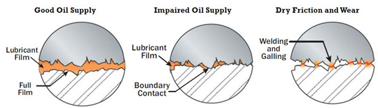
Micropitting generally occurs under elastohydrodynamic lubrication (EHL). When the oil film thickness under EHL becomes too thin at the gear pitchline, surface asperities will begin to come into contact. When these asperities contact each other on opposing surfaces and under high load, they cause elastic or plastic deformation, which leads to micropitting.

81%of lubrication professionals have seen the effects of micropitting or surface fatigue in the gears at their plant, based on a recent survey at machinerylubrication.com

Surface fatigue is very similar. Under elastohydrodynamic lubrication, surface fatigue often results from denting on a surface due to hard or soft particles. The dents in the surface create what are known as berms. Over time and with repeated high loading, pits develop where the surface breaks apart. With continued high loading, the pits become larger.

The Effects

Surface fatigue and micropitting are influenced by the particular lubricant being used, including its base oil, additives, viscosity selection and particle contamination. While micropitting or surface fatigue can occur with synthetic or mineral oil lubricants, synthetics can provide better protection at higher temperatures than mineral oils with the same viscosity grade and additive package. This is due to the fact that synthetics can have a higher viscosity index. In other words, the viscosity of synthetics may change less with an increase in temperature.

Although extreme pressure (EP) additives are often necessary, in certain cases they can be very chemically aggressive to surfaces and cause micropitting. These types of additives also become more active with higher temperatures. Some researchers claim oils that do not have EP additives will exhibit a maximum resistance to micropitting. An oil’s ability to protect against micropitting can be determined using the FZG FVA 54 test.

High-viscosity oils also have a greater resistance to micropitting because of their thicker EHL films. However, going to a higher viscosity is not always the best option because it can cause higher operating temperatures, energy loss and/or an increased rate of oil oxidation.

High Risk Contacts

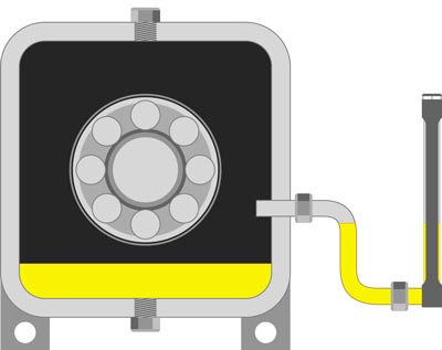
Anywhere rolling contact occurs in machinery there is potential for micropitting and surface fatigue. This would include rolling-element bearings (along the base of the raceway). Gears also have rolling contact, which usually occurs around the pitchline. Cams and rollers are other examples of where you can see rolling contact and thus possible surface fatigue and micropitting.

Particles that are much larger than the EHL film thickness can become entrained between surfaces due to a rolling action. Once these particles are in the contact area, they are subjected to massive amounts of contact pressure. Particles with lower compressive strength under this contact pressure can break into smaller pieces, with some embedding in the surfaces and others passing through the contact zone. Harder particles that are larger than the EHL film thickness can pass through the contact zone by denting the softer surface. As mentioned previously, these dents create berms (shoulders) and, over time with more contact pressure, can dislodge from the surface.

Controlling Micropitting and Surface Fatigue

Selecting the right viscosity is key in reducing micropitting and surface fatigue. Higher loads will require higher viscosity, while lower loads allow for lower viscosities. Speed can also have an effect on micropitting and surface fatigue. At lower speeds, the film thickness will decrease. Likewise, at higher speeds, the film thickness can increase. This is another factor to consider in selecting the correct viscosity for your application. The operating temperature also plays a role in micropitting and surface fatigue. As the temperature increases at the contact area, the oil’s viscosity becomes lower and film thickness decreases. As the temperature increases, a lubricant with too low of a viscosity will become thinner and not provide adequate protection, leading to an increased rate of micropitting and surface fatigue. If an EP oil is used, the EP additives become more reactive at higher temperatures and can offer protection from adhesive wear.

Of course, too high of a viscosity can also generate excessive heat. This heat that is caused by too high of a viscosity will lead to accelerated oxidation. If oil analysis is not used to determine the remaining useful life and trigger the need for an oil change, the oil will break down and not provide sufficient protection.

Thursday, 3 July 2014

The Hidden Dangers of Lubricant Starvation

Article extract from Reliable plant newsletter:
http://www.machinerylubrication.com/Read/29040/lubricant-starvation-dangers   

    
For those who strive for lubrication-enabled reliability (LER), more than 95 percent of the opportunity comes from paying close attention to the “Big Four.” These are critical attributes to the optimum reference state (ORS) needed to achieve lubrication excellence. The “Big Four” individually and collectively influence the state of lubrication, and are largely controllable by machinery maintainers. They are well-known but frequently not well-achieved. The “Big Four” are:
  1. Correct lubricant selection
  2. Stabilized lubricant health
  3. Contamination control
  4. Adequate and sustained lubricant level/supply
The first three of the “Big Four” have benefited from considerable industry attention, especially in recent years. Conversely, the last one has gone relatively unnoticed yet is no less important. Therefore, it will be the central focus of this article.
Over the past few decades, researchers and tribologists have compiled countless listings that rank the chief causes of machine failure. We’ve published many of these in Machinery Lubrication magazine. The lists ascribe the causes of abnormal machine wear to the usual suspects: contamination, overheating, misalignment, installation error, etc. There’s typically a lubrication root-cause category that is a catch-all for one or more causes that can’t be easily specified or named. I’ve seen terms used like “inadequate lubrication” and “wrong lubrication.”
Understandably, it is difficult for failure investigators and analysts to trace back the exact sequence of events beginning with one or more root causes. Evidence of these causes is often destroyed in the course of failure or in a cover-up during the cleanup and repair. Having led several hundred such investigations over the years, I’ve learned that one root cause in particular is too often overlooked - lubricant starvation.
81% of lubrication professionals have seen the effects of lubricant starvation in the machines at their plant, according to a recent survey at machinerylubrication.com
Although most everyone knows about this in principle and realizes the common sense of adequate lubricant supply, it is frequently ignored because many typical forms of lubricant starvation are largely hidden from view. For instance, who notices the quasi-dry friction that accelerates wear each time you start an automobile engine? This is a form of lubricant starvation. It’s not a sudden-death failure, but it is a precipitous wear event nonetheless. Each time controllable wear goes uncontrolled, an opportunity is lost to prolong service life and increase reliability.

The Nature of Lubricant Starvation

Machines don’t just need some lubricant or any lubricant. Rather, they need a sustained and adequate supply of the right lubricant. Adequate doesn’t just mean dampness or the nearby presence of lubricant. What’s defined as adequate varies somewhat from machine to machine but is critical nonetheless. High-speed equipment running at full hydrodynamic film has the greatest lubricant appetite and is also the most punished when starved. Machines running at low speeds and loads are more forgiving when lube supply is restricted. Even these machines can fail suddenly when severe starvation occurs.
The table below illustrates how lubricants reach frictional surfaces in numerous ways.
There are six primary functions of a lubricating oil. These are friction control, wear control, temperature control, corrosion control, contamination control and transmittance of force and motion (hydraulics). Each of these functions is adversely influenced by starvation conditions. The worst would be friction, wear and temperature control. Even partial starvation intensifies the formation of frictional heat. It also slows the transport of that heat out of the zone. This is a compounding, self-propagating condition that results in collapsed oil films, galling, adhesive wear and abrasion (Figure 1).

Figure 1. Starvation Illustrated
In the case of grease, starvation-induced heating (from friction) of the load zone accelerates grease dry-out, which escalates starvation further. Heat rapidly drains oil out of the grease thickener, causing volatilization and base oil oxidation, all of which contributes to hardening and greater starvation.
Lubricating oil needs reinforcement, which is lost when flow becomes restricted or static. Flow brings in bulk viscosity for hydrodynamic lift. In fact, lack of adequate lubricant supply is functionally equivalent to inadequate viscosity from the standpoint of film strength.

4 Keys to Solving Starvation Problems Using Proactive Maintenance

  1. Identify the required lube supply or level to optimize reliability.
  2. Establish and deploy a means to sustain the optimized supply or level.
  3. Establish a monitoring program to verify the optimized supply or level is consistently achieved.
  4. Rapidly remedy non-compliant lube supply or level problems.
Oil flow also refreshes critical additives to the working surfaces. This reserve additive supply includes anti-wear additives, friction modifiers, corrosion inhibitors and others. Lubricant starvation produces elevated heat, which rapidly depletes additives.
Next, we know that wear particles are also self-propagating. Particles make more wear particles by three-body abrasion, surface fatigue and so on. Impaired oil flow inhibits the purging of these particles from the frictional zones. The result is an accelerated wear condition.
Finally, moving oil serves as a heat exchanger by displacing localized heat generated in load zones outward to the walls of the machine, oil reservoir or cooler. The amount of heat transfer is a function of the flow rate. Starvation impairs flow and heat transfer. This puts increasing thermal stress on the oil and the machine.

Common Signs of Starvation

When you’re encountering chronic machine reliability problems, think through the “Big Four” and don’t forget about No. 4. It may not be the type of oil, the age of the oil or even the contamination in the oil, but rather the quantity of oil. How can you know? The chart on page 8 reveals some common signs of lubricant starvation.

Lubricant Starvation Examples by Machine Type

Lubricant starvation can happen in a number of ways. Most are controllable, but a few are not. The following abbreviated list identifies how lubricant starvation occurs in common machines.

Starved Engines

  • Dry Starts - Oil drains out down to the oil pan when the engine is turned off. On restart, frictional zones (turbo bearings, shaft bearings, valve deck, etc.) are momentarily starved of lubrication (Figure 2).

    Figure 2. Dry Engine Starts
  • Cold Starts - Cold wintertime conditions slow the movement of oil in the engine during start-up. This can induce air in the flow line due to cold-temperature suction-line conditions.
  • Low Oil Pressure - This can result from numerous causes, including worn bearings, pump wear, sludge and extreme cold. Oil pressure is the motive force that sends oil to the zones requiring lubrication.
  • Dribbling Injectors - Fuel injector problems can wash oil off cylinder walls and impair lubrication between the piston/rings and the cylinder wall.

    Common Signs of Lubricant Starvation
  • Clogged Spray Nozzles and Orifices - Nozzles and orifices direct oil sprays to cylinder walls, valves and other moving components. Sludge and contaminants are able to restrict oil flow.

Starved Journal and Tilting-Pad Thrust Bearings

  • Oil Groove Problems - Grooves and ports channel oil to the bearing load zones. Grooves become clogged with debris or sludge, restricting oil flow.
  • Restricted Oil Supply - Pumping and oil-lifting devices can become mechanically faulty. This also may be due to low oil levels, high viscosity, aeration/foam and cold temperatures.
  • Sludge Dam on Bearing Leading Edge - Sludge can build up on the bearing’s leading edge and restrict the oil supply.

Wet-Sump Bearing and Gearbox Starvation

  • Oil Level - Many wet-sump applications require critical control of the oil level (Figure 3).

    Figure 3. Common Splash Gear Drive
  • High Viscosity - Many oil-feed mechanisms (oil rings, slingers, splash feeders, etc.) are hampered by viscosity that is too high (wrong oil, cold oil, etc.). Gears can channel through thick, cold oil, interfering with splash and other feed devices.
  • Aeration and Foam - Air contamination dampens oil movement and impairs the performance of oil-feed devices (Figure 4).

    Figure 4. How Aeration Retards Oil Supply
  • Non-horizontal Shafts - This can cause drag on oil rings and may interfere with slinger/flinger feed mechanisms.
  • Bottom Sediment and Water (BS&W) - Sump BS&W displaces the oil level. On vertical shafts, the bottom bearing can become completely submerged in BS&W.
  • Defective Constant-Level Oilers - This may be due to plugged connecting pipe nipples, mounting errors (tilted, cocked, mounted on wrong side, etc.), wrong level setting, empty reservoir, etc. (Figure 5).

    Figure 5. Mounting Errors of Constant-Level Oilers
  • Defective Level Gauge Markings - Level gauges should be accurately calibrated to the correct oil level.
  • Level Gauge Mounting and Viewing Issues - These may be hard to see, goosenecks, fouled gauge glass, gauge vent problems, etc. (Figure 6).

    Figure 6. What is wrong with this picture?

Starved Dry-Sump Circulating Systems

  • Restricted Oil Returns - Plugged or partially plugged oil returns will redirect oil flow away from the bearing or gearbox being lubricated. Sometimes called drip-and-burn lubrication, the condition is usually caused by sludge buildup or air-lock conditions in the gravity drain lines returning to the tank.
  • Worn Oil Pump - When oil pumps wear, they lose volumetric efficiency (flow decay results).
  • Restricted Pump Suction Line - Strainers and pickup tubes can become plugged or restricted. This can aerate the fluid, cause cavitation and lead to loss of prime.
  • Clogged/Restricted Oil Ways and Nozzles - Oil-feed restrictions due to sludge, varnish and jammed particles can starve bearings and gears (Figure 7).

    Figure 7. Plugged Oil Flow
  • Entrained Air and Foam - Oil pumps and flow meters perform poorly (or not at all) when sumps become contaminated with air (Figure 4).
  • Lack of Flow Measurement - Components sensitive to oil supply require constant oil flow measurement.
  • Defective or Miscalibrated Flow Meters - Flow meters, depending on the type and application, can present a range of problems regarding calibration.
  • Low Oil Pressure - Oil follows the path of least resistance. Line breaks and open returns starve oil from higher resistance flow paths and the machine components they serve.

Starved Spray-Lubed Chains and Open Gears

  • Defective Auto-lube Settings - This relates to correctly setting the lube volume and frequency.
  • Defective Spray Targets/Pattern - The oil spray needs to fully wet the target location. Spray nozzles can lose aim and become clogged (Figure 8).

    Figure 8. Correct Lubricant Spray Patterns
    on Open-Gear Tooth Flanks
  • Gummed Chain Joints - Many chains become heavily gummed, which prevents oil from penetrating the pin/bushing interface.

Starvation from Grease Single- and Multi-Point Auto Lubrication

  • Wrong Regrease Settings - Regreasing settings should enable adequate grease replenishment at each lube point.
  • Cake-Lock - This occurs when grease is being pumped. Under certain conditions, the grease thickener movement is restricted. Oil flows, but the thickener is log-jammed in a line or component passage (Figure 9).

    Figure 9. Cake-Lock
    Grease Starvation
  • Defective Injector Flow - This is due to wrong injector settings or restricted injector displacement.
  • Restricted Line Flow - Exceedingly long lines, narrow lines, numerous bends, ambient heat or cold, etc., can lead to partial or complete blockage of grease flow.
  • Single-point Lubricator Issues - These include malfunctioning lubricators from various causes.

Starvation from Manual Lubrication Issues

  • Grease Gun Lubrication - This may include an inaccurate volume calibration, a faulty grease gun mechanism, the wrong relube frequency, an incorrect relube volume or an improper relube procedure.
  • Manual Oil Lubrication - This would include the wrong relube frequency, volume or procedure.
  • Lube Preventive Maintenance (PM) - Missed PMs may be due to scheduling, management or maintenance culture issues.

The Crux of the Problem

Lubricant starvation is an almost silent destroyer. While there are telltale signs, they generally aren’t recognized or understood. Of course, there are varying degrees of starvation. Complete starvation is sudden and blatant. However, more moderate partial starvation is what tends to go unnoticed until failure. Then, other suspect causes (the bearing, lubricant, operator, etc.) may be falsely blamed.
Precision lubrication supply is a fundamental attribute of the optimum reference state and is included in any engineering specification for lubrication excellence. It’s one of the “Big Four” and thus is overdue for significant attention.

About the Author
Jim Fitch
Jim Fitch, a founder and president of Noria Corporation, has a wealth of experience in lubrication, oil analysis, and machinery failure investigations. He has advised hundreds of companies on ... 

Monday, 4 February 2013

Duty Standby Regime

In the world of process plant, redundant system is being installed. Equipment such as PLC or Control System runs on a full time online fall back redundancy system. Whereas most mechanical equipment runs on a variety of duty-standby arrangement.

In my view, the most effective duty-standby arrangement has to be judged by the engineer. The question to ask is, what is the dominant failure mode. If it is a random failure mode that is dominating, there is very low risk of increase of failure for switching them every fixed period of time. If the dominant failure mode is in the realm of wear, then one might want to consider off-setting the operational hours so they don't have a perfect storm resulting in plant downtime. If the dominant failure mode is false brinelling, one might want to consider running all the redundant equipment at partial load instead!

Wednesday, 16 January 2013

Managing the depth of RCM

RCM stands for Reliability Centred Maintenance. It is a process whereby a series of questions are structurally raised to conclude a maintenance requirement. It can be as tedious as a full blown RCM where you are moving on average about 3-4 Failure Modes an hour in a RCM workshop to a quick straight forward 30-50 Failure Modes an hour in a peer review workshop.

How deep to go for the RCM analysis? There're a few things to consider when making this call.

  1. How skilled are your maintenance team in addressing the Failure Modes? There is no point going into too detail if your trades does not share the understanding and knowledge. For example, carrying out vibration analysis on an equipment without a skilled person is useless. No one will be able to interpret the data and put it to good use. Your strategy would then have to be fine tuned to fixed-time replacement on an optimized shutdown interval.
  2. How critical is the equipment? The more critical it is, the more time should be invested towards making it performing reliably.
  3. What is the current state of the maintenance strategy? Is it running reliably? If it is, are we seeing potential Failure Modes that we are not addressing? A peer review to close the gap in the strategy is sufficient in this case. If the equipment is not reliable to start with, it may require a full blown RCM from scratch.
  4. There will be times where you run into a highly critical equipment but yet the Failure Modes are highly unlikely. The facilitator or reliability engineer would have to make the call whether a full blown RCM is worthwhile or manage the risk with a peer review process to ensure all gaps in strategies are covered. This require local plant experience that none of your external consultants have. Re-emphasize, invest in your reliability team!
  5. ???


A note to reliability managers out there, if a person pitch you they can deliver RCM workshop at 15 Failure Modes an hour, be very wary about it. You get what you pay for. Quality takes time and it is inevitable in RCM! Again, your best value is through having invest in a very good reliability engineer on your side. After all, the RCM databases will still require maintenance and update in-house, unless you are ready to pay the continual work from the consultancy.

Friday, 16 November 2012

Gear Coupling reference 1

Found a useful article in Reliable Plant newsletter today in regards to couplings.

How to Achieve Gear Coupling Reliability

http://www.machinerylubrication.com/Read/28851/gear-coupling-reliability

How to Achieve Gear Coupling Reliability


Design, Selection and Sizing

Selecting the correct coupling for the application is critical for gear coupling reliability. Use the following steps to help make the selection process easier:
  1. Choose the coupling style and design (Fast’s, Series H or Waldron; flex and rigid halves; close coupled or floating shaft; gear teeth specifications and misalignment requirements).
  2. Select the service factor (SF) from the original equipment manufacturer’s (OEM) gear coupling charts. Shock loads or variable loading can cause premature failure if adequate SF is not used. Typical service factors are in the 1.5 to 2.0 range. Some manufacturers may even specify a misalignment factor for gear coupling sizing when higher coupling misalignment is expected.
  3. Calculate application torque (T) requirements based on design brake horsepower (BHP), SF and speed.
  4. Choose a coupling with a torque capacity greater than the torque requirements. Since the service factor is already factored in, there is no reason to add additional capacity.
  5. Confirm that the coupling selected has a bore capacity greater than the actual application bore (shaft size). Frequently the maximum bore size will drive the coupling sizing process and even increase the coupling torque capacity two to three times what was previously calculated.
  6. Verify the shaft depth available for the coupling hub and compare to the actual hub depth. If the hub is too long, it must be either overhung or machined off. Since the hub to shaft engagement is the same in either method, it is preferred to have the hub machined off due to torsional effects of the overhung hub. If the hub is overhung or cut off, further examination may be necessary to determine if there is enough torque transmission capacity available. The rule of thumb is a 1-to-1 ratio for the hub length to the bore.
  7. Check a dynamic balance chart to see if the coupling needs to be balanced. High-speed gear couplings may require balancing.
  8. Ensure the coupling will fit around the equipment and guarding. This is typically something that can become an issue when there is a design modification on existing equipment. Guards that allow maintainability will encourage proper maintenance in the long run.

Installation

Some couplings don’t get much of a chance at a decent life due to their installation. Just like other components that experience infant mortality, often times these parts don’t die but are murdered. Certain elements of gear coupling installation must be considered if optimum reliability is to be obtained, including:
  • Hub and Sleeve Fits - Determine the type of hub fit (clearance, locational or interference). Higher speed applications should have an adequate interference fit to offset centrifugal force effects on shaft/hub contact pressures. Excessive hub interference fits can lead to hub cracks and hub failure.
  • Keys and Keyway Fits - Keyways should have a proper radius to reduce the risk for fatigue cracking. Key lengths should be measured to minimize the coupling imbalance.
  • Hub Bore - Ensure the hub bore is concentric to minimize hub runout.
  • Hub Installation - Choose proper heating methods so hub material properties are not compromised and select the proper heating magnitude for interference fit hubs so the hub slides easily on the shaft. Never use a hammer to install or remove hubs, as this can cause bearing damage.
  • Correct Coupling Gaps - If floating shafts have a small coupling gap, the shafts may impact one another under misalignment as the shaft oscillates during operation.
  • Proper Sealing - Always use proper gaskets and O-rings so the lubricant stays in the coupling.
  • Alignment - Install the coupling so misalignment stays within manufacturer limits with respect to offset, angular and axial misalignment.
  • Fastener Assembly - Choose the correct type of fasteners (fine or coarse, length, exposed, shrouded, etc.) and the proper arrangement. While standard bolts can work, they may put the threads in the shear plane. Coupling bolts need the correct preload, which is accomplished by proper bolt torque methods.
  • Lubrication - Get the right product in the right amount at the right time for optimum gear coupling reliability.

Different coupling styles have different lube and bore capacities. (Ref. Kopflex)

Lubrication

Perhaps the most important operating factor for a gear coupling to be reliable is lubrication. Selection of the proper lubricant is the first step. Many coupling manufacturers supply their own lubricants for their couplings. Gear couplings may either be grease- or oil-lubricated depending on the design. Oil-lubricated couplings will not dry out like grease couplings, while Fast-style couplings have smaller bore capacities.
It is fair to say that most gear couplings are grease-lubricated. Coupling greases have special properties, so general-purpose greases should never be used in gear coupling applications. Gear couplings can be subjected to very high centrifugal forces, and oil separation is a critical element of coupling greases. Since greases are comprised of oil and mostly a thickener, special considerations must be made regarding the selection and application of coupling greases.
Soap thickeners typically are heavier than the oils, so centrifugal forces tend to deposit the thickener at the gear teeth. Generally, a grease with a high oil content of high-viscosity oil and a grade 1 rating from the National Lubricating Grease Institute (NLGI) is preferred. A higher consistency grease may be considered for high-speed applications but should be avoided at low-speed applications.
Grease specifications may include speed limits or certain tests such as the K36 separation factor. Any grease will have oil separation based on time, temperature and centrifugal force. The K36 factor determines the maximum oil separation of the grease while running at 36,000 Gs. A K36 factor of 8/24 means the oil separation was 8 percent in 24 hours. In comparison, a grease with a K36 factor of 3/24 would mean that it did not separate as much as the grease with a K36 factor of 8/24.
Higher oil separation is desirable at lower speeds (lower G forces), while lower oil separation is preferred at higher speeds and higher temperatures. High-vibration equipment can also enhance oil separation and induce failures. Studies have even shown that gear coupling wear rates decrease as coupling speeds increase.
The main function of a lubricant in a gear coupling is to reduce the friction between the gear teeth as they slide against each other. The relative motion between the mating gear teeth occurs in the axial direction due to slight shaft misalignment. This motion is oscillatory, low amplitude, relatively high frequency and a function of the magnitude of angular misalignment.
This sliding axial motion between the gear teeth can generate lots of wear if lubrication is not sufficient. This is why the gear coupling lubricant plays such a critical role in the reliability and life of a gear coupling. Poor lubrication between the gear teeth generates higher friction between these teeth, resulting in gear coupling wear, heat generation and high axial loads to mating equipment bearings. The higher axial loads on the bearings will then decrease the life of the equipment.
The pump shown on the left had a dry coupling that was operating in a torque-lock condition and creating high axial forces on the equipment. The coupling was replaced without making any adjustments to the pump or motor. The only change was a coupling with good lubrication, which reduced tooth friction and decreased the axial forces from the coupling to the pump and motor. The result was a noticeable decrease in the operating temperature of the pump bearing.


Maintenance

Maintenance is the final factor to ensure gear coupling reliability for long equipment life. While the first three factors have more to do with a lack of knowledge, maintenance often comes down to a lack of execution. Unfortunately, this requires discipline by operations and maintenance groups as well as managerial courage to dedicate the resources to ensure that it can happen.
Typical recommendations from gear coupling manufacturers require regreasing at a minimum of 12 months. A regreasing procedure would include breaking, cleaning, inspecting and hand-packing the coupling with fresh grease. Using a grease gun typically is not recommended when the coupling has been broken and ready to receive new grease. When a gear coupling is greased through a fitting instead of hand-packing, it can result in overgreasing, and a hydraulic lock condition can occur, causing high axial forces on the equipment. A hydraulic lock condition can even make alignment difficult, as shafts may be hard to turn.


Some applications require regreasing at six months to ensure good reliability. These applications may include high speeds (high G forces), high temperatures, misalignment or vibration. Smaller lube sump capacity can also be a factor in regreasing intervals. However, deciding to go longer than 12 months without grease replenishment on a gear coupling is a high-risk move that is not recommended.
Regular maintenance of gear couplings should involve special care with respect to many of the installation factors discussed previously. When inspecting gaskets and O-rings, ensure the lubricant stays in the coupling until the next maintenance task is scheduled. Grease fittings should be removed before completing maintenance. These fittings have been known to leak lubricant and can hit guarding, causing loss of lubricant. Under high centrifugal forces, the grease must be completely sealed within the coupling. Guarding should also allow enough access so it does not have to be completely removed for normal coupling maintenance.
Remember, reliability is not for the faint of heart. Most all of these factors must be executed correctly to achieve good gear coupling reliability. This is why the work of maintenance and reliability professionals is rarely ever finished.


About the Author

Randy Riddell is a senior mechanical reliability engineer for International Paper in Courtland, Ala. He is a certified lubrication specialist (CLS) by the Society of Tribologists and Lubrication Engineers and a certified level I machinery lubrication technician (MLT) by the International Council for Machinery Lubrication (ICML). He is also a certified maintenance and reliability professional (CMRP) by the Society for Maintenance and Reliability Professionals (SMRP).

Friday, 2 November 2012

Bearing Failure reference 1

I subscribed to a reliability newsletter from machinery lubrication. Read this article in the email today and find it a good basic guide to bearing failure.

http://www.machinerylubrication.com/Read/28854/prevent-bearing-failures

5 Ways to Prevent Bearing Failures


The accurate diagnosis of a bearing failure is imperative to prevent repeat failures and additional expense. Rolling bearings are precision machine elements found in a wide variety of applications. They are typically very reliable even under the toughest conditions. Under normal operating conditions, bearings have a substantial service life, which is expressed as either a period of time or as the total number of rotations before the rolling elements or inner and outer rings fatigue or fail. According to research, less than 1 percent of rolling bearings do not reach their expected life.

You must be aware of the radial internal
clearance (RIC) and maintain the proper
RIC that was established in the
original design.

Premature Bearing Failure

When a bearing does fail prematurely, it usually is due to causes that could have been avoided. For this reason, the possibility of reaching conclusions about the cause of a defect by means of studying its appearance is very useful. It’s most important to correct the causes and prevent future failures and the costs that follow.
Most bearing failures such as flaking, pitting, spalling, unusual wear patterns, rust, corrosion, creeping, skewing, etc., are usually attributed to a relatively small group of causes that are often interrelated and correctable. These causes include lubrication, mounting, operational stress, bearing selection and environmental influence.

Proper Lubrication

The purpose of lubricating a bearing is to cover the rolling and sliding contact surfaces with a thin oil film to avoid direct metal-to-metal contact. When done effectively, this reduces friction and abrasion, transports heat generated by friction, prolongs service life, prevents rust and corrosion, and keeps foreign objects and contamination away from rolling elements.
Grease typically is used for lubricating bearings because it is easy to handle and simplifies the sealing system, while oil lubrication is more suitable for high-speed or high-temperature operations.
Generally, lubrication failures occur due to:
  • Using the wrong type of lubricant
  • Too little grease/oil
  • Too much grease/oil
  • Mixing of grease/oil
  • Contamination of the grease/oil by objects or water

Grease Service Life

In addition to the normal bearing service life, it is also important to take into consideration the normal grease service life. Grease service life is the time over which proper bearing function is sustained by a particular quantity and category of grease. This is especially crucial in pump, compressor, motor and super-precision applications.

Mounting and Installation of Bearings

In the mounting and installation process, it is critical to use proper tools and ovens/induction heaters. Employ a sleeve to impact the entire inner ring face being press fit. Also, verify the shaft and housing tolerances. If the fit is too tight, you will create too much preload. If the fit is too loose, you will generate too little preload, which may allow the shaft to rotate or creep in the bearing. Don’t forget to check for proper diameters, roundness and chamfer radius.
Be sure to avoid misalignment or shaft deflection. This is particularly significant in mounting bearings that have separable components such as cylindrical roller bearings where successful load bearing and optimal life are established or diminished at installation.
You must also be aware of the radial internal clearance (RIC) and maintain the proper RIC that was established in the original design. The standard scale in order of ascending clearance is C2, C0, C3, C4 and C5. The proper clearance for the application is important in that it allows for the challenges of lubrication, shaft fit and heat.
Keep in mind that a proper film of lubricant must be established between the rolling elements. Reducing internal clearance and impeding lubricant flow can lead to premature failure. With regards to shaft fit, it is inevitable that there can be a reduction in the radial internal clearance when the bearing is press fit. Also, in the normal operation of bearings, heat is produced, which creates thermal expansion of the inner and outer rings. This can reduce the internal clearance, which will reduce the optimal bearing life.


Causes of failure in rolling bearings

Operational Stress and Bearing Selection

Generally, it is the exception to find a bearing that has been improperly designed into an application. However, factors within the larger application may change. If loads become too high, overloading and early fatigue may follow. If they are too low, skidding and improper loading of the rolling elements occur. Early failure will follow in each situation. Similar issues arise with improper internal clearance.
The first sign of these issues will be unusual noises and/or increased temperatures. Bearing temperatures typically rise with start-up and stabilize at a temperature slightly lower than at start-up (normally 10 to 40 degrees C higher than room temperature). A desirable bearing temperature is below 100 degrees C.
There are typical abnormal bearing sounds that reveal certain issues in the bearing application. While this is a subjective test, it is helpful to know that a screech or howling sound usually indicates too large an internal clearance or poor lubrication on a cylindrical roller bearing, while a crunching felt when the shaft is rotated by hand normally suggests contamination of the raceways.
Operational stresses in the application can impact bearing life as well. It is essential to isolate vibrations in associated equipment, as they can cause uneven running and unusual noises.

Environmental Influence

Even with the best design, lubrication and installation, failures will occur if the operating environment is not taken into consideration. While there are many potential issues, the primary ones include:
  • Dust and dirt, which can aggressively contaminate a bearing. Special care should be given to using proper sealing techniques.
  • Aggressive media or water. Once again, sealing is key. The use of specialty-type seals that do not score the shaft is recommended.
  • External heat. The ambient operating temperature mandates many choices in radial internal clearance, high-temperature lubricants, intermittent or continuous running and other factors that affect bearing life.
  • Current passage or electrolytic corrosion. If current is allowed to flow through the rolling elements, sparks can create pitting or fluting on the bearing surfaces. This can be corrected by creating a bypass circuit for the current or by using insulation on or within the bearing. This should be an inherent design consideration in applications such as wind turbines and all power-generating equipment.
Remember, the first step in the overall prevention of bearing failure lies in the consideration of bearing technologies that are most suitable to the application with regard to specifications, recommendations, maintenance strategies, fatigue life and wear resistance of the bearing. Premature bearing failure within a proper application is typically attributed to one or more of the causes discussed (lubrication, mounting, operational stress, bearing selection or environmental influence), which can and should be corrected in order to avoid future bearing failures and additional cost.

About the Author

Steven Katz is the president of Emerson Bearing, a provider of bearings to OEMs (original equipment manufacturers) and MRO (maintenance, repair and operations) markets in the United States and internationally. For more information, contact 800-225-4587 or visitwww.emersonbearing.com.