Showing posts with label Reference. Show all posts
Showing posts with label Reference. Show all posts
Wednesday, 2 July 2014
Equipment Registry aka Master Equipment List aka Asset Register
The term used for the registry or list varies from organisation to organisation, but it basically refer to the list of all money making assets which were constructed in the process plant or facility.
To set the scene, I'm quoting from Reliable Plant article, authored by Bob Schindler,
"The equipment registry is one of the most important tools in your kit when it comes to maintenance and reliability. It can be the foundation of your planned maintenance, lubrication, training and repair programs, as well as help with regulatory compliance and safety programs.
Your spare parts management program depends upon a complete and accurate registry with the requisite analysis for regular service parts along with the insurance spares identified through failure modes and effects analysis. Don’t forget that your financials are also tied in through depreciation, amortization and cost center assignments.
Equipment history gets tied to the registry along with manuals, drawings, procedures, labor costs and reports. That is why it is the foundation upon which so much is built, and that is why it is so vital that you get it right and work to maintain its accuracy.
While it has an initial cost and a maintenance cost, the payback can be significant and continuous, so make the investment even if you have to bump something else down the list. The man-hours that you save long term will repay your investment many times over. You can consider the downtime and spares savings as icing on the cake."
I personally could not emphasize enough how important that is. It may sound very obvious that it is the most fundamental things to do is to have an Asset Register, but unfortunately, common sense is not as common as we all thought. I have been to many plants, and I have never seen an Asset Register that is 100% yet. The best would be somewhere around 98%, the worst I have personally seen would probably in the 70% mark along with poor labelling and documentation. I would not be surprised to walk into a plant without an Asset Register. Why? I have come across plant managers who doesn't know their plant's statutory requirement, and licenses required to be a plant manager.
To people initiating projects out there, please ensure your contractor provide you with a complete register. To the managements, please don't slash the cost for such thing. It will cost the organisation big money for a loooooong time.
Friday, 16 November 2012
Plant Mothballing
Read an article in Reliable Plant newsletter today. Made me aware of some work involved prior to mothballing a plant. Good start to that area of practice anyway. :)
http://www.reliableplant.com/Read/28796/do-before-plant-closure
What You Should Do Before a Plant Closure
Just as with any critical situation, a long-term strategic approach coupled with a series of medium-term tactics and detailed plans are needed. You should also consider how long the shutdown is probably going to last (guesstimate) and whether the plant will most likely be restarted, sold as a complete unit or sold piecemeal.
Examine every item or class of equipment individually and write a specific initial storage/mothball technique plus a methodology for ongoing maintenance.
For the purposes of this article, let’s consider an item of equipment or a whole plant that might restart as early as six to nine months but could also be several years.
Unused plants and equipment that are properly prepared for shutdown and left in fairly good condition can retain much of their value. However, if a plant is left “as is” and allowed to deteriorate, as is normally the case, much of it can be fit only as scrap in just a matter of months. Engaging in a well-planned process of deactivation/mothballing can be worthwhile either way, whether it should ever be reactivated or just sold for its second-hand value at some future point.
A useful analogy in developing a strategy is to compare what it takes to maintain fire. In the case of fire, there are three essential legs: heat, a fuel source and oxygen. Likewise, age-related deterioration involves a driving force (such as galvanic action), a conducting medium (electrolyte) and oxygen. The fundamental approach to stopping or slowing this age-related deterioration is to remove one or more of the three legs.
In simple terms, we aim to do the following:
http://www.reliableplant.com/Read/28796/do-before-plant-closure
What You Should Do Before a Plant Closure
- Accept the news that your plant is facing an impending plant shutdown. It is not necessarily a “knockout” for the plant or your career. Remember, in the often uneven battleground called the global marketplace, just about anything can happen. Be ready to get up and start fighting again.
- Designate responsibility to an individual for writing a list of possible scenarios. The individual should have enough clout to implement the chosen strategy, if necessary.
- Go to the top of the company and request that sufficient funds be made available to execute the initial shutdown and preservation strategy.
- Choose the right type of long-term equipment caretakers. Those selected are often security or ex-supervisory types rather than experienced operator/craftsmen with intimate knowledge of the equipment.
- Don’t allow critical components to be pirated (stolen for use elsewhere) if part of a larger plant.
- Remove all process materials. Even innocuous materials left in the unit in the long term will likely cost five times more than at the initial shutdown. The current operations people are familiar with all the hazards.
- Seek expert advice on equipment preservation resulting in not getting the best bang for the buck.
- Involve the hourly workforce in the shutdown and mothball plan. Almost unbelievably, our recent experience has been that if the decision to shut down at some future date has been made, then involving operators and mechanics can very much improve both the quality of the shutdown plan and its execution.
- Not only record but clearly and physically mark what has been done to preserve the item of equipment during deactivation. The reactivating crew (probably a different group of people) can easily miss that a filter, line blind, internal component, etc., has been removed or added with serious consequences at a future start-up.
Just as with any critical situation, a long-term strategic approach coupled with a series of medium-term tactics and detailed plans are needed. You should also consider how long the shutdown is probably going to last (guesstimate) and whether the plant will most likely be restarted, sold as a complete unit or sold piecemeal.
Examine every item or class of equipment individually and write a specific initial storage/mothball technique plus a methodology for ongoing maintenance.
For the purposes of this article, let’s consider an item of equipment or a whole plant that might restart as early as six to nine months but could also be several years.
Unused plants and equipment that are properly prepared for shutdown and left in fairly good condition can retain much of their value. However, if a plant is left “as is” and allowed to deteriorate, as is normally the case, much of it can be fit only as scrap in just a matter of months. Engaging in a well-planned process of deactivation/mothballing can be worthwhile either way, whether it should ever be reactivated or just sold for its second-hand value at some future point.
Materials and Equipment You Will Need
Having a clear view of how the constant foes of galvanic/bio corrosion, mold, mildew, etc., can be mitigated if not defeated is essential. Although much will depend on local conditions, the wetter and colder situations are much more challenging in terms of handling humidity, while blowing dust is an issue for those in the high desert regions. For this article, we will consider a central United States or European location.A useful analogy in developing a strategy is to compare what it takes to maintain fire. In the case of fire, there are three essential legs: heat, a fuel source and oxygen. Likewise, age-related deterioration involves a driving force (such as galvanic action), a conducting medium (electrolyte) and oxygen. The fundamental approach to stopping or slowing this age-related deterioration is to remove one or more of the three legs.
In simple terms, we aim to do the following:
- Separate dissimilar metals.
- Protect surfaces that could be attacked, even with a covering of only a few molecules thick.
- Dry out or remove the conducting medium (electrolyte — air or gas). Corrosion cannot occur when parts are stored in environments where the relative humidity is held below 40 percent.
- Remove any oxygen or sources of chemical or biological attack.
- Liquid protective waxes and liquid polyvinyl chloride (PVC) coating — These can be sprayed on any clean, dry surface to protect them. Wherever it is applied, PVC will form a tough, flexible, waterproof skin that will withstand the extremes of temperature, thermal shock, differential substrate movement and impingement even when sprayed on webbing to form a cocoon.
- Volatile corrosion inhibitors (VCIs) — These generate protective vapors even at room temperatures. They come in a number of convenient forms, including time-release vaporizers, sprays, plastic bags and films, powders, oil additives and coatings. They are adsorbed onto the metallic surfaces of the equipment (just a few molecules thick), where they can prevent corrosion for up to two years. While most VCIs are environmentally friendly and create no safety hazards for employees, there are some that are suspected of being harmful. Most contain no toxic substances, such as nitrates or chromates. (Note: Volatile organic compounds should not be used in combination with a desiccant.)
- Vapor space inhibitor (VSI) — This is an oily concentrate that can be added to lubricating oil systems (internal combustion engines, etc.) when equipment is not going to be completely filled.
- Heat-shrinkable plastic films — These are ideal for enclosing individual machines that have been cleaned and dried and have internal desiccants added.
- VCI-covered polythene films — These are used to wrap individual smaller components.
- Chemical oxygen scavengers — These are frequently added to fresh water used to displace more corrosive liquid in systems that can’t be effectively cleaned or dried out.
- Chemical inhibitors — These are added to liquids and chemicals and are designed to remove unwanted products while preferentially inhibiting their attack on the body of the container. (Antifreeze sometimes used in this process contains them.)
- Desiccants — These include numerous substances (solids) that absorb water from gases (air) or liquids.
- Biocides — These are used to prevent microbial growths in water and fuels such as gasoline and diesel fuel.
- Light waxes — These are used as surface protectors for metals.
- Sacrificial Anodes — These are used in tanks that cannot be drained of their contents.
Strategies by Equipment Class
Before considering individual techniques, make a best guess of the duration and whether it is going to be an “attended monitored” lay-up or a “walk-away” lay-up. This article is simply a guide and is not intended to be totally comprehensive and detailed.Tanks, Pressure Vessels and Pipework
It is essential that tanks, pressure vessels and pipework be left as clean and dry as possible. Insert line blinds to create manageable zones that can be slightly pressurized (0.5 psig+) using nitrogen or dry air. Include some small flow and arrange for some simple telltale mechanism to show pressure flow and the level of humidity (indicator cards). For large enclosures, use a commercial dehumidifier of an appropriate capacity. For vessels, tanks and containments that must be kept full of liquid, some form of oxygen scavenger or anti-biological growth chemical can be used (see boilers). If a pipework system contains any traps, have its internals removed and clear all strainers.Boilers
Boilers can be laid up using either the long-term dry method or the hydrazine wet lay-up method, which involves leaving the wet side (boiler, economizer and super heater) full of feed-treated water. The feed water is dosed with 15 percent hydrazine and then pH-adjusted to raise the alkalinity to a minimum pH of 8.3. The fire side is supplied with heated air, with desiccant as a backup. Both water-side and fire-side points should have new gaskets, except for furnace hot-air entry inspection and exit points.Pumps, Engines, Compressors and Machinery
To minimize internal corrosion, close off all vents and openings, and completely fill the casing with the manufacturer’s recommended lubricant. Alternatively, add a volatile corrosion inhibitor in the correct proportion to the lubricating oil. For large compressors, turbines, etc., first centrifuge/circulate the existing oil using a portable filtration cart through water-absorbing filter elements to remove any free water. For diesel and gasoline engines, drain the fuel systems and add biocide to the remaining fuel. To prevent external corrosion, if unpainted, one of the recommended spray-on coatings should be used (either a light wax or liquid PVC).Instruments/Controls
Maintaining the driest possible conditions for both electronics and external field devices, including sensors, transmitters and valves, can be achieved by strategic placement of desiccant packages and sealing the enclosures. This should be supplemented by placing small containers of VCI powder wherever possible. These will not adversely affect electronics. Instruments that normally would be in contact with the process materials should be removed, cleaned, protected and marked for immediate local storage.Electrical Enclosures
Seal and insert bags or wraps of desiccants and containers of volatile corrosion inhibitors. Alternatively, heat using individual strip or built-in heaters.Motors and Generators
Clean the exterior, grease and apply a protective covering. If completely sealed, add packets of desiccant. Lift carbon brushes from commutators/slip rings. Where sleeve-type bearings are fitted, a VSI concentrate should be added to the lubrication system.Exercising and Monitoring
Depending on the time involved, it will be necessary to periodically exercise equipment by rotating it several times and leaving it at a different (90-degree) angle. Where humidity controls have been set, these need at least weekly monitoring. Where chemical controls are used, these should be checked every three months. Periodic monitoring of motor/generator internal resistance, as well as tank oxygen levels and humidity levels, is necessary for long-term lay-up.Auxiliaries
In most cases, various fire-protection systems and alarms still need to be maintained and powered up. Fires are common in dried-out cooling towers. If batteries are normally used, disconnect them and smear the terminals with petroleum jelly. Vented-type lead-acid batteries should first be fully charged, then drained and flushed with distilled water.A Final Note
A recent discussion with two major plant-dismantling/second-hand equipment vendors revealed that currently there are very few people looking for used equipment, and many idle plants are being offered for sale. They reported that when the decision to shut down comes, most companies remove anything that could present an immediate danger but essentially close the doors and walk away from millions of dollars’ worth of equipment.Gear Coupling reference 1
Found a useful article in Reliable Plant newsletter today in regards to couplings.
How to Achieve Gear Coupling Reliability
http://www.machinerylubrication.com/Read/28851/gear-coupling-reliability
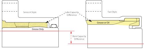
Different coupling styles have different lube and bore capacities. (Ref. Kopflex)
It is fair to say that most gear couplings are grease-lubricated. Coupling greases have special properties, so general-purpose greases should never be used in gear coupling applications. Gear couplings can be subjected to very high centrifugal forces, and oil separation is a critical element of coupling greases. Since greases are comprised of oil and mostly a thickener, special considerations must be made regarding the selection and application of coupling greases.
Soap thickeners typically are heavier than the oils, so centrifugal forces tend to deposit the thickener at the gear teeth. Generally, a grease with a high oil content of high-viscosity oil and a grade 1 rating from the National Lubricating Grease Institute (NLGI) is preferred. A higher consistency grease may be considered for high-speed applications but should be avoided at low-speed applications.
Grease specifications may include speed limits or certain tests such as the K36 separation factor. Any grease will have oil separation based on time, temperature and centrifugal force. The K36 factor determines the maximum oil separation of the grease while running at 36,000 Gs. A K36 factor of 8/24 means the oil separation was 8 percent in 24 hours. In comparison, a grease with a K36 factor of 3/24 would mean that it did not separate as much as the grease with a K36 factor of 8/24.
Higher oil separation is desirable at lower speeds (lower G forces), while lower oil separation is preferred at higher speeds and higher temperatures. High-vibration equipment can also enhance oil separation and induce failures. Studies have even shown that gear coupling wear rates decrease as coupling speeds increase.
The main function of a lubricant in a gear coupling is to reduce the friction between the gear teeth as they slide against each other. The relative motion between the mating gear teeth occurs in the axial direction due to slight shaft misalignment. This motion is oscillatory, low amplitude, relatively high frequency and a function of the magnitude of angular misalignment.
This sliding axial motion between the gear teeth can generate lots of wear if lubrication is not sufficient. This is why the gear coupling lubricant plays such a critical role in the reliability and life of a gear coupling. Poor lubrication between the gear teeth generates higher friction between these teeth, resulting in gear coupling wear, heat generation and high axial loads to mating equipment bearings. The higher axial loads on the bearings will then decrease the life of the equipment.
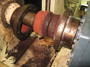
The pump shown on the left had a dry coupling that was operating in a torque-lock condition and creating high axial forces on the equipment. The coupling was replaced without making any adjustments to the pump or motor. The only change was a coupling with good lubrication, which reduced tooth friction and decreased the axial forces from the coupling to the pump and motor. The result was a noticeable decrease in the operating temperature of the pump bearing.
Typical recommendations from gear coupling manufacturers require regreasing at a minimum of 12 months. A regreasing procedure would include breaking, cleaning, inspecting and hand-packing the coupling with fresh grease. Using a grease gun typically is not recommended when the coupling has been broken and ready to receive new grease. When a gear coupling is greased through a fitting instead of hand-packing, it can result in overgreasing, and a hydraulic lock condition can occur, causing high axial forces on the equipment. A hydraulic lock condition can even make alignment difficult, as shafts may be hard to turn.

Some applications require regreasing at six months to ensure good reliability. These applications may include high speeds (high G forces), high temperatures, misalignment or vibration. Smaller lube sump capacity can also be a factor in regreasing intervals. However, deciding to go longer than 12 months without grease replenishment on a gear coupling is a high-risk move that is not recommended.
Regular maintenance of gear couplings should involve special care with respect to many of the installation factors discussed previously. When inspecting gaskets and O-rings, ensure the lubricant stays in the coupling until the next maintenance task is scheduled. Grease fittings should be removed before completing maintenance. These fittings have been known to leak lubricant and can hit guarding, causing loss of lubricant. Under high centrifugal forces, the grease must be completely sealed within the coupling. Guarding should also allow enough access so it does not have to be completely removed for normal coupling maintenance.
Remember, reliability is not for the faint of heart. Most all of these factors must be executed correctly to achieve good gear coupling reliability. This is why the work of maintenance and reliability professionals is rarely ever finished.

How to Achieve Gear Coupling Reliability
http://www.machinerylubrication.com/Read/28851/gear-coupling-reliability
How to Achieve Gear Coupling Reliability
Design, Selection and Sizing
Selecting the correct coupling for the application is critical for gear coupling reliability. Use the following steps to help make the selection process easier:- Choose the coupling style and design (Fast’s, Series H or Waldron; flex and rigid halves; close coupled or floating shaft; gear teeth specifications and misalignment requirements).
- Select the service factor (SF) from the original equipment manufacturer’s (OEM) gear coupling charts. Shock loads or variable loading can cause premature failure if adequate SF is not used. Typical service factors are in the 1.5 to 2.0 range. Some manufacturers may even specify a misalignment factor for gear coupling sizing when higher coupling misalignment is expected.
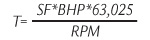
- Calculate application torque (T) requirements based on design brake horsepower (BHP), SF and speed.
- Choose a coupling with a torque capacity greater than the torque requirements. Since the service factor is already factored in, there is no reason to add additional capacity.
- Confirm that the coupling selected has a bore capacity greater than the actual application bore (shaft size). Frequently the maximum bore size will drive the coupling sizing process and even increase the coupling torque capacity two to three times what was previously calculated.
- Verify the shaft depth available for the coupling hub and compare to the actual hub depth. If the hub is too long, it must be either overhung or machined off. Since the hub to shaft engagement is the same in either method, it is preferred to have the hub machined off due to torsional effects of the overhung hub. If the hub is overhung or cut off, further examination may be necessary to determine if there is enough torque transmission capacity available. The rule of thumb is a 1-to-1 ratio for the hub length to the bore.
- Check a dynamic balance chart to see if the coupling needs to be balanced. High-speed gear couplings may require balancing.
- Ensure the coupling will fit around the equipment and guarding. This is typically something that can become an issue when there is a design modification on existing equipment. Guards that allow maintainability will encourage proper maintenance in the long run.
Installation
Some couplings don’t get much of a chance at a decent life due to their installation. Just like other components that experience infant mortality, often times these parts don’t die but are murdered. Certain elements of gear coupling installation must be considered if optimum reliability is to be obtained, including:- Hub and Sleeve Fits - Determine the type of hub fit (clearance, locational or interference). Higher speed applications should have an adequate interference fit to offset centrifugal force effects on shaft/hub contact pressures. Excessive hub interference fits can lead to hub cracks and hub failure.
- Keys and Keyway Fits - Keyways should have a proper radius to reduce the risk for fatigue cracking. Key lengths should be measured to minimize the coupling imbalance.
- Hub Bore - Ensure the hub bore is concentric to minimize hub runout.
- Hub Installation - Choose proper heating methods so hub material properties are not compromised and select the proper heating magnitude for interference fit hubs so the hub slides easily on the shaft. Never use a hammer to install or remove hubs, as this can cause bearing damage.
- Correct Coupling Gaps - If floating shafts have a small coupling gap, the shafts may impact one another under misalignment as the shaft oscillates during operation.
- Proper Sealing - Always use proper gaskets and O-rings so the lubricant stays in the coupling.
- Alignment - Install the coupling so misalignment stays within manufacturer limits with respect to offset, angular and axial misalignment.
- Fastener Assembly - Choose the correct type of fasteners (fine or coarse, length, exposed, shrouded, etc.) and the proper arrangement. While standard bolts can work, they may put the threads in the shear plane. Coupling bolts need the correct preload, which is accomplished by proper bolt torque methods.
- Lubrication - Get the right product in the right amount at the right time for optimum gear coupling reliability.
Different coupling styles have different lube and bore capacities. (Ref. Kopflex)
Lubrication
Perhaps the most important operating factor for a gear coupling to be reliable is lubrication. Selection of the proper lubricant is the first step. Many coupling manufacturers supply their own lubricants for their couplings. Gear couplings may either be grease- or oil-lubricated depending on the design. Oil-lubricated couplings will not dry out like grease couplings, while Fast-style couplings have smaller bore capacities.It is fair to say that most gear couplings are grease-lubricated. Coupling greases have special properties, so general-purpose greases should never be used in gear coupling applications. Gear couplings can be subjected to very high centrifugal forces, and oil separation is a critical element of coupling greases. Since greases are comprised of oil and mostly a thickener, special considerations must be made regarding the selection and application of coupling greases.
Soap thickeners typically are heavier than the oils, so centrifugal forces tend to deposit the thickener at the gear teeth. Generally, a grease with a high oil content of high-viscosity oil and a grade 1 rating from the National Lubricating Grease Institute (NLGI) is preferred. A higher consistency grease may be considered for high-speed applications but should be avoided at low-speed applications.
Grease specifications may include speed limits or certain tests such as the K36 separation factor. Any grease will have oil separation based on time, temperature and centrifugal force. The K36 factor determines the maximum oil separation of the grease while running at 36,000 Gs. A K36 factor of 8/24 means the oil separation was 8 percent in 24 hours. In comparison, a grease with a K36 factor of 3/24 would mean that it did not separate as much as the grease with a K36 factor of 8/24.
Higher oil separation is desirable at lower speeds (lower G forces), while lower oil separation is preferred at higher speeds and higher temperatures. High-vibration equipment can also enhance oil separation and induce failures. Studies have even shown that gear coupling wear rates decrease as coupling speeds increase.
The main function of a lubricant in a gear coupling is to reduce the friction between the gear teeth as they slide against each other. The relative motion between the mating gear teeth occurs in the axial direction due to slight shaft misalignment. This motion is oscillatory, low amplitude, relatively high frequency and a function of the magnitude of angular misalignment.
This sliding axial motion between the gear teeth can generate lots of wear if lubrication is not sufficient. This is why the gear coupling lubricant plays such a critical role in the reliability and life of a gear coupling. Poor lubrication between the gear teeth generates higher friction between these teeth, resulting in gear coupling wear, heat generation and high axial loads to mating equipment bearings. The higher axial loads on the bearings will then decrease the life of the equipment.
The pump shown on the left had a dry coupling that was operating in a torque-lock condition and creating high axial forces on the equipment. The coupling was replaced without making any adjustments to the pump or motor. The only change was a coupling with good lubrication, which reduced tooth friction and decreased the axial forces from the coupling to the pump and motor. The result was a noticeable decrease in the operating temperature of the pump bearing.
Maintenance
Maintenance is the final factor to ensure gear coupling reliability for long equipment life. While the first three factors have more to do with a lack of knowledge, maintenance often comes down to a lack of execution. Unfortunately, this requires discipline by operations and maintenance groups as well as managerial courage to dedicate the resources to ensure that it can happen.Typical recommendations from gear coupling manufacturers require regreasing at a minimum of 12 months. A regreasing procedure would include breaking, cleaning, inspecting and hand-packing the coupling with fresh grease. Using a grease gun typically is not recommended when the coupling has been broken and ready to receive new grease. When a gear coupling is greased through a fitting instead of hand-packing, it can result in overgreasing, and a hydraulic lock condition can occur, causing high axial forces on the equipment. A hydraulic lock condition can even make alignment difficult, as shafts may be hard to turn.
Regular maintenance of gear couplings should involve special care with respect to many of the installation factors discussed previously. When inspecting gaskets and O-rings, ensure the lubricant stays in the coupling until the next maintenance task is scheduled. Grease fittings should be removed before completing maintenance. These fittings have been known to leak lubricant and can hit guarding, causing loss of lubricant. Under high centrifugal forces, the grease must be completely sealed within the coupling. Guarding should also allow enough access so it does not have to be completely removed for normal coupling maintenance.
Remember, reliability is not for the faint of heart. Most all of these factors must be executed correctly to achieve good gear coupling reliability. This is why the work of maintenance and reliability professionals is rarely ever finished.
About the Author
Randy Riddell is a senior mechanical reliability engineer for International Paper in Courtland, Ala. He is a certified lubrication specialist (CLS) by the Society of Tribologists and Lubrication Engineers and a certified level I machinery lubrication technician (MLT) by the International Council for Machinery Lubrication (ICML). He is also a certified maintenance and reliability professional (CMRP) by the Society for Maintenance and Reliability Professionals (SMRP).Friday, 2 November 2012
Bearing Failure reference 1
I subscribed to a reliability newsletter from machinery lubrication. Read this article in the email today and find it a good basic guide to bearing failure.
http://www.machinerylubrication.com/Read/28854/prevent-bearing-failures
http://www.machinerylubrication.com/Read/28854/prevent-bearing-failures
5 Ways to Prevent Bearing Failures
The accurate diagnosis of a bearing failure is imperative to prevent repeat failures and additional expense. Rolling bearings are precision machine elements found in a wide variety of applications. They are typically very reliable even under the toughest conditions. Under normal operating conditions, bearings have a substantial service life, which is expressed as either a period of time or as the total number of rotations before the rolling elements or inner and outer rings fatigue or fail. According to research, less than 1 percent of rolling bearings do not reach their expected life.
You must be aware of the radial internal
clearance (RIC) and maintain the proper
RIC that was established in the
original design.
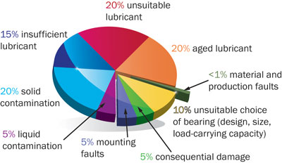
Most bearing failures such as flaking, pitting, spalling, unusual wear patterns, rust, corrosion, creeping, skewing, etc., are usually attributed to a relatively small group of causes that are often interrelated and correctable. These causes include lubrication, mounting, operational stress, bearing selection and environmental influence.
Grease typically is used for lubricating bearings because it is easy to handle and simplifies the sealing system, while oil lubrication is more suitable for high-speed or high-temperature operations.
Generally, lubrication failures occur due to:
Be sure to avoid misalignment or shaft deflection. This is particularly significant in mounting bearings that have separable components such as cylindrical roller bearings where successful load bearing and optimal life are established or diminished at installation.
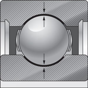
You must also be aware of the radial internal clearance (RIC) and maintain the proper RIC that was established in the original design. The standard scale in order of ascending clearance is C2, C0, C3, C4 and C5. The proper clearance for the application is important in that it allows for the challenges of lubrication, shaft fit and heat.
Keep in mind that a proper film of lubricant must be established between the rolling elements. Reducing internal clearance and impeding lubricant flow can lead to premature failure. With regards to shaft fit, it is inevitable that there can be a reduction in the radial internal clearance when the bearing is press fit. Also, in the normal operation of bearings, heat is produced, which creates thermal expansion of the inner and outer rings. This can reduce the internal clearance, which will reduce the optimal bearing life.
Causes of failure in rolling bearings
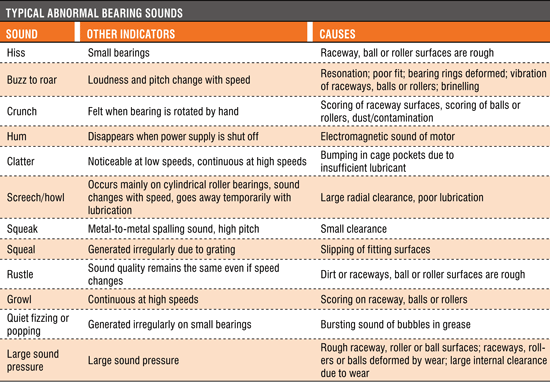
The first sign of these issues will be unusual noises and/or increased temperatures. Bearing temperatures typically rise with start-up and stabilize at a temperature slightly lower than at start-up (normally 10 to 40 degrees C higher than room temperature). A desirable bearing temperature is below 100 degrees C.
There are typical abnormal bearing sounds that reveal certain issues in the bearing application. While this is a subjective test, it is helpful to know that a screech or howling sound usually indicates too large an internal clearance or poor lubrication on a cylindrical roller bearing, while a crunching felt when the shaft is rotated by hand normally suggests contamination of the raceways.
Operational stresses in the application can impact bearing life as well. It is essential to isolate vibrations in associated equipment, as they can cause uneven running and unusual noises.
You must be aware of the radial internal
clearance (RIC) and maintain the proper
RIC that was established in the
original design.
Premature Bearing Failure
When a bearing does fail prematurely, it usually is due to causes that could have been avoided. For this reason, the possibility of reaching conclusions about the cause of a defect by means of studying its appearance is very useful. It’s most important to correct the causes and prevent future failures and the costs that follow.Most bearing failures such as flaking, pitting, spalling, unusual wear patterns, rust, corrosion, creeping, skewing, etc., are usually attributed to a relatively small group of causes that are often interrelated and correctable. These causes include lubrication, mounting, operational stress, bearing selection and environmental influence.
Proper Lubrication
The purpose of lubricating a bearing is to cover the rolling and sliding contact surfaces with a thin oil film to avoid direct metal-to-metal contact. When done effectively, this reduces friction and abrasion, transports heat generated by friction, prolongs service life, prevents rust and corrosion, and keeps foreign objects and contamination away from rolling elements.Grease typically is used for lubricating bearings because it is easy to handle and simplifies the sealing system, while oil lubrication is more suitable for high-speed or high-temperature operations.
Generally, lubrication failures occur due to:
- Using the wrong type of lubricant
- Too little grease/oil
- Too much grease/oil
- Mixing of grease/oil
- Contamination of the grease/oil by objects or water
Grease Service Life
In addition to the normal bearing service life, it is also important to take into consideration the normal grease service life. Grease service life is the time over which proper bearing function is sustained by a particular quantity and category of grease. This is especially crucial in pump, compressor, motor and super-precision applications.Mounting and Installation of Bearings
In the mounting and installation process, it is critical to use proper tools and ovens/induction heaters. Employ a sleeve to impact the entire inner ring face being press fit. Also, verify the shaft and housing tolerances. If the fit is too tight, you will create too much preload. If the fit is too loose, you will generate too little preload, which may allow the shaft to rotate or creep in the bearing. Don’t forget to check for proper diameters, roundness and chamfer radius.Be sure to avoid misalignment or shaft deflection. This is particularly significant in mounting bearings that have separable components such as cylindrical roller bearings where successful load bearing and optimal life are established or diminished at installation.
You must also be aware of the radial internal clearance (RIC) and maintain the proper RIC that was established in the original design. The standard scale in order of ascending clearance is C2, C0, C3, C4 and C5. The proper clearance for the application is important in that it allows for the challenges of lubrication, shaft fit and heat.
Keep in mind that a proper film of lubricant must be established between the rolling elements. Reducing internal clearance and impeding lubricant flow can lead to premature failure. With regards to shaft fit, it is inevitable that there can be a reduction in the radial internal clearance when the bearing is press fit. Also, in the normal operation of bearings, heat is produced, which creates thermal expansion of the inner and outer rings. This can reduce the internal clearance, which will reduce the optimal bearing life.
Causes of failure in rolling bearings
Operational Stress and Bearing Selection
Generally, it is the exception to find a bearing that has been improperly designed into an application. However, factors within the larger application may change. If loads become too high, overloading and early fatigue may follow. If they are too low, skidding and improper loading of the rolling elements occur. Early failure will follow in each situation. Similar issues arise with improper internal clearance.The first sign of these issues will be unusual noises and/or increased temperatures. Bearing temperatures typically rise with start-up and stabilize at a temperature slightly lower than at start-up (normally 10 to 40 degrees C higher than room temperature). A desirable bearing temperature is below 100 degrees C.
There are typical abnormal bearing sounds that reveal certain issues in the bearing application. While this is a subjective test, it is helpful to know that a screech or howling sound usually indicates too large an internal clearance or poor lubrication on a cylindrical roller bearing, while a crunching felt when the shaft is rotated by hand normally suggests contamination of the raceways.
Operational stresses in the application can impact bearing life as well. It is essential to isolate vibrations in associated equipment, as they can cause uneven running and unusual noises.
Environmental Influence
Even with the best design, lubrication and installation, failures will occur if the operating environment is not taken into consideration. While there are many potential issues, the primary ones include:- Dust and dirt, which can aggressively contaminate a bearing. Special care should be given to using proper sealing techniques.
- Aggressive media or water. Once again, sealing is key. The use of specialty-type seals that do not score the shaft is recommended.
- External heat. The ambient operating temperature mandates many choices in radial internal clearance, high-temperature lubricants, intermittent or continuous running and other factors that affect bearing life.
- Current passage or electrolytic corrosion. If current is allowed to flow through the rolling elements, sparks can create pitting or fluting on the bearing surfaces. This can be corrected by creating a bypass circuit for the current or by using insulation on or within the bearing. This should be an inherent design consideration in applications such as wind turbines and all power-generating equipment.
About the Author
Steven Katz is the president of Emerson Bearing, a provider of bearings to OEMs (original equipment manufacturers) and MRO (maintenance, repair and operations) markets in the United States and internationally. For more information, contact 800-225-4587 or visitwww.emersonbearing.com.
Subscribe to:
Posts (Atom)