Equipment manufacturers generally provide guidelines on how oil should be maintained for reliable operation. Because components have little tolerance for contamination or oxidation, frequent oil sampling and monitoring are performed while the equipment is online in order to keep the unit operating without any issues. However, many times little attention is paid to the oil quality when the equipment is shut down for a maintenance outage or on standby. This can eventually affect the unit’s reliability.
For instance, when a steam turbine is down for prolonged periods or for a short three-week maintenance outage, the consequences of not having hot, circulating oil running through the system is usually not considered. In fact, the oil quality when placing a turbine on turning gear or during startup is often not the same as when the unit came offline.

Prolonged exposure to water can
rust a control system.
Typical turbine bearings are designed for fluid-film lubrication. Most fluid-film bearings are intended for hydrodynamic lubrication. This means an oil wedge is formed in a hydrodynamic bearing to develop separation and maintain an oil film between the rotor and bearing. The film thickness is a function of rotor speed, load and oil viscosity. Under fluid-film conditions, an increase in viscosity or speed increases the oil film thickness, while an increase in load or decrease in rotor speed reduces the oil film thickness.
In developing an oil film, the bearing surface geometry and rotor surface are just as important as rotor speed, load and oil viscosity. To establish a stable oil wedge and fluid film between the surfaces, the rotor and bearing profiles must be perpendicular. If either or both surfaces become damaged by large particles being pushed through the bearing, the ability to form an oil wedge is diminished, resulting in a thinner oil film thickness. Reducing the oil film thickness increases the susceptibility of additional damage or producing a rub during coastdown or startup.
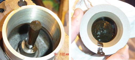
The congealed mass shown above is an example of particulate matter and
degraded oil buildup that can accumulate in a turbine control servo.
Left unattended, this condition could eventually cause poor
turbine control response and accelerate equipment wear.
When the turbine rotor is at normal operating conditions, the bearing is in hydrodynamic lubrication conditions. However, when a turbine rotor is on turning gear or beginning to roll at slower speeds, the journal bearing is in boundary lubrication conditions. These conditions are generally indicated by some metallic friction and wear.
Very high coefficients of friction may also be reached. At this point, the oil film thickness between the bearing and the turbine rotor will be at its minimum. The film thickness will increase as either the speed is increased, the lubricant viscosity is increased, the load is decreased or the geometric shapes of the journal and bearing surfaces relative to each other are improved. If the surface becomes rougher (the bearing surface becomes damaged), then the risk of rotor and bearing surface contact increases. This relationship between the surface roughness and the film thickness is important in the consideration of hydrodynamic lubrication of a turbine bearing.


These images show the buildup of particulate in a turbine oil reservoir that is cleaned periodically. Consider the type of buildup that could occur over the life of the plant.
A major concern with rough surfaces, including gouges or grooves around the journal or along a Babbitt surface, is that they allow high-pressure lube oil to flow away from the thinnest film areas. This permits increased contact and shear forces on the Babbitt than would occur with smooth, concentric and round journals on a smoothly bored Babbitt surface bearing. This is why surfaces that appear to have minimal damage can still cause bearing failure during startup or slow-speed operation before a fully developed hydrodynamic film with a normal film thickness exists.
During a plant startup, when a turbine is on turning gear or at lower speeds, the lubrication system may supply lube oil with slugs of particulate matter to the journal and thrust bearings. This is especially damaging to journal bearings because they carry the applied load forces that force the journals into contact with the bearing surface, thus providing a very thin oil film. This form of lubrication is known as boundary lubrication. Because only a very thin oil film exists between the journal and bearing surface, and many of the particles in the oil are larger than this oil film thickness, the bearing surface can be scored as particulate becomes imbedded in the surface of the Babbitt. In some cases, the particulate can score the journal, requiring it to be remachined and/or honed.
While a unit is operating, the amount of water in the lubricating or control system is normally maintained within the manufacturer’s specification by the plant’s oil-conditioning system. These systems often contain some type of demulsifying agent to remove water. Even if the water content is well above normally acceptable standards, the steel surfaces are usually kept wetted with oil, and corrosion (rust) is limited. However, when the turbine is shut down for weeks or months, water will generally separate from the oil in the pipes and components where the oil resides. If water separation occurs, it can corrode the equipment, support microbiological growth and/or affect the functioning of the control system. Additionally, when drained, large portions of the system normally filled with oil become exposed to the environment (air and oxygen). Obviously, the longer the duration a turbine lubrication system remains secured, the more time the equipment has to oxidize.

This orifice plug from a boiler feed
pump turbine control has deposits
covering the orifice holes.
Particle contamination not only can cause equipment to wear, but it also clogs lubrication ports, in-line filters and control systems. During operation, the parameters used to monitor oil tend to remain stable, but when the system that is designed to maintain lubrication and keep piping and hardware clear is secured, the rate of oxidation on the exposed surfaces increases. Then, when the unit is returned to service, the newly formed corrosion (rust) on any exposed piping or surfaces often is shaken loose or washed away with the restarted oil flow. Furthermore, where there are pockets in which stagnant oil may have settled, a slug of particulate and coagulating oil can easily form. When the oil flow is restarted, this particulate matter is easily pulled into the lubrication flow streams and circulated throughout the lubrication system.
One substantial area of concern is the control system. Because of the system’s complexity and low-flow velocity within the control piping, the system acts as a collection point for particulate.
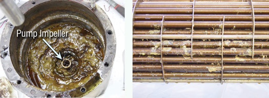
Biological growth, particulate and separated lubricant additives have
collected on this pump (above left). The lube oil cooler on the
right has biological growth and adhered lubricant additives.

Figure 1. The results from a mesh blockage particle counter revealed that a large amount
of contaminants were released into the lubrication system after 12 hours of operation.
As Figure 1 indicates, after approximately 12 hours in operation, a large slug of contaminants must have released into the system, causing the need to change filters. At that point, a decision was made to reduce the filter size and continue. Once the turbine was rolled, the auxiliary filtration unit was secured. Inspection of the last set of filters revealed a significant collection of particulate captured within the filters.
In another example, a filtration skid with a particle counter was tied into a turbine reservoir during the plant’s startup. This power plant normally only operates during peak summer months in the southern part of the United States, leaving it shut down for at least six months out of the year. The particle counter recorded main turbine reservoir contaminant levels above 4, 6 and 14 microns. Figure 2 illustrates the change in particulate levels from the time the turbine was on turning gear until the unit was synchronized to the power grid.

Figure 2. This graph illustrates the changes in oil particulate during the startup
of a turbine. The dash lines provide the lSO 4406 “alert” level for specific particle sizes.
Notice when the turbine rolled off turning gear and increased its speed to 2,400 revolutions per minute for thermal soaking, a large burst of particulate was released into the lubrication system. This caused all three particle levels to increase above the normal operating limits and remain high for more than two hours. Added filtration was able to bring the particle levels down to acceptable limits, but when the turbine speed was increased to synchronize the generator to the power grid, another spike occurred.
Plants generally do not monitor particle levels as equipment is placed back into service. When a turbine is at normal operating speed, the minimum oil film thickness between the turbine rotor and the bearing surfaces is in the order of 0.002 inches for journal diameters from 8 to 16 inches. The minimum film thickness increases to 0.010 inches for the largest journal bearings with 30-inch diameters. However, when the turbine is on turning gear, this oil film thickness is only a few microns thick at best.
As the speed increases, so does the film thickness between the rotor and bearings. If a large mass of particulate gets into a journal bearing when the film thickness is only microns thick, the particulate matter can scar or damage the journal and/or bearing profile, which in turn affects the fluid dynamics within the bearing. This often leads to overheated bearings and possibly to bearing failure.
To control particulate matter, it is better to use filter element sizes than ISO charts, since ISO charts allow a few large particles, which can lead to journal bearing failure.
Understanding what is occurring provides the best way to identify and assess risk. Once a risk is identified, actions can be taken, consequences evaluated, mitigations and contingencies developed, and an implementation plan pursued.
There are many ways to reduce risks when bringing large equipment back into service. A review of vibration data and other parameters can tell a lot about how the equipment performs when going from cold to normal operating conditions. It also will inform you of what is needed to extend the health of the equipment or increase the operating efficiency.

Connecting a kidney-loop filtration system to a tank or reservoir can help
reduce the risks when bringing equipment back into service.
Perhaps the most versatile and cost-effective method to help reduce the risk to equipment is to have a kidney-loop filtration system available. This type of system can be connected to a tank or reservoir to support bringing the equipment back into service.
The filtration unit should be sized to process the contents of the tank or reservoir several times per hour. In addition, the unit can be equipped with a cooler for summer months when thermal loads on the plant limit equipment operation. Along with filtering and cooling, a kidney-loop system can include a dehydrator, which provides an excellent way to extract water from the oil before placing the equipment on turning gear. This will reduce the amount of water that gets pushed through high-pressure differential regions of the oil film in the journal bearing and reduce the risk or amount of flashing, which causes damage and erosion of Babbitted and non-Babbitted surfaces.
Keep in mind that the expense of an auxiliary filtration skid can be quickly offset by a reduction in maintenance costs. In fact, the cost of replacing a damaged bearing or by keeping plant equipment running during peak summer months could easily justify reducing the risk of repeat failures. For example, a 10-percent power reduction at a nuclear plant during peak summer temperatures would pay for auxiliary filtration systems on most challenged equipment within days.
.
For instance, when a steam turbine is down for prolonged periods or for a short three-week maintenance outage, the consequences of not having hot, circulating oil running through the system is usually not considered. In fact, the oil quality when placing a turbine on turning gear or during startup is often not the same as when the unit came offline.
Prolonged exposure to water can
rust a control system.
In developing an oil film, the bearing surface geometry and rotor surface are just as important as rotor speed, load and oil viscosity. To establish a stable oil wedge and fluid film between the surfaces, the rotor and bearing profiles must be perpendicular. If either or both surfaces become damaged by large particles being pushed through the bearing, the ability to form an oil wedge is diminished, resulting in a thinner oil film thickness. Reducing the oil film thickness increases the susceptibility of additional damage or producing a rub during coastdown or startup.
The congealed mass shown above is an example of particulate matter and
degraded oil buildup that can accumulate in a turbine control servo.
Left unattended, this condition could eventually cause poor
turbine control response and accelerate equipment wear.
Very high coefficients of friction may also be reached. At this point, the oil film thickness between the bearing and the turbine rotor will be at its minimum. The film thickness will increase as either the speed is increased, the lubricant viscosity is increased, the load is decreased or the geometric shapes of the journal and bearing surfaces relative to each other are improved. If the surface becomes rougher (the bearing surface becomes damaged), then the risk of rotor and bearing surface contact increases. This relationship between the surface roughness and the film thickness is important in the consideration of hydrodynamic lubrication of a turbine bearing.
These images show the buildup of particulate in a turbine oil reservoir that is cleaned periodically. Consider the type of buildup that could occur over the life of the plant.
A major concern with rough surfaces, including gouges or grooves around the journal or along a Babbitt surface, is that they allow high-pressure lube oil to flow away from the thinnest film areas. This permits increased contact and shear forces on the Babbitt than would occur with smooth, concentric and round journals on a smoothly bored Babbitt surface bearing. This is why surfaces that appear to have minimal damage can still cause bearing failure during startup or slow-speed operation before a fully developed hydrodynamic film with a normal film thickness exists.
During a plant startup, when a turbine is on turning gear or at lower speeds, the lubrication system may supply lube oil with slugs of particulate matter to the journal and thrust bearings. This is especially damaging to journal bearings because they carry the applied load forces that force the journals into contact with the bearing surface, thus providing a very thin oil film. This form of lubrication is known as boundary lubrication. Because only a very thin oil film exists between the journal and bearing surface, and many of the particles in the oil are larger than this oil film thickness, the bearing surface can be scored as particulate becomes imbedded in the surface of the Babbitt. In some cases, the particulate can score the journal, requiring it to be remachined and/or honed.
Water Contamination
Water contamination in a lubricating or control system is particularly undesirable because it tends to form an emulsion with the oil. Elevated water content in an oil system can also affect lubricity and induce corrosion. When a lubrication or control system is shut down, the normally wetted regions, such as those in the lube oil drain pipes, become exposed to air. Enlarging the surface area of carbon steel that is subject to ambient conditions increases the amount of internal corrosion (rust) a system develops.While a unit is operating, the amount of water in the lubricating or control system is normally maintained within the manufacturer’s specification by the plant’s oil-conditioning system. These systems often contain some type of demulsifying agent to remove water. Even if the water content is well above normally acceptable standards, the steel surfaces are usually kept wetted with oil, and corrosion (rust) is limited. However, when the turbine is shut down for weeks or months, water will generally separate from the oil in the pipes and components where the oil resides. If water separation occurs, it can corrode the equipment, support microbiological growth and/or affect the functioning of the control system. Additionally, when drained, large portions of the system normally filled with oil become exposed to the environment (air and oxygen). Obviously, the longer the duration a turbine lubrication system remains secured, the more time the equipment has to oxidize.
Particle Contamination
This orifice plug from a boiler feed
pump turbine control has deposits
covering the orifice holes.
One substantial area of concern is the control system. Because of the system’s complexity and low-flow velocity within the control piping, the system acts as a collection point for particulate.
Biological Growth
When a lubrication system is secured for prolonged periods of time, biological growth can occur. Low-flow areas can collect a tremendous amount of sludge over the years. With this amount of growth, a sudden change in the lubricating system’s temperature, such as that which occurs when returning the system to service, can result in the biological growth dying off and the remains being pushed through the system.Biological growth, particulate and separated lubricant additives have
collected on this pump (above left). The lube oil cooler on the
right has biological growth and adhered lubricant additives.
Cleanliness Codes
Most plants have equipment monitoring programs that define lubricant property limits. These limits are usually established for normal operating conditions. One of the parameters typically monitored is particulate levels. The International Organization for Standardization (ISO) has developed a method (ISO 4406) for quantifying the level of particle contamination. The values gathered in a particle count test identify the number of particles in a given volume of fluid that are above a specific size range, which is generally set at 4 microns, 6 microns and 14 microns. The data is normally presented in a format such as 17/15/13, which provides a numeric range value representing the measured quantity of particles greater than 4 microns, 6 microns and 14 microns, respectively.Case Studies
In a recent turbine outage, the lubrication system was placed into operation, and the main turbine was placed on turning gear. While the system was operating, an auxiliary filtration skid was connected to the main turbine reservoir to run in parallel with the normal filtration system. The skid had dual 7-micron filters and processed the main turbine reservoir four times per hour. An oil sample recorder pulled samples at 20-minute increments from the center of the turbine oil reservoir and then documented 31 hours of results from the mesh blockage particle counter.Figure 1. The results from a mesh blockage particle counter revealed that a large amount
of contaminants were released into the lubrication system after 12 hours of operation.
As Figure 1 indicates, after approximately 12 hours in operation, a large slug of contaminants must have released into the system, causing the need to change filters. At that point, a decision was made to reduce the filter size and continue. Once the turbine was rolled, the auxiliary filtration unit was secured. Inspection of the last set of filters revealed a significant collection of particulate captured within the filters.
In another example, a filtration skid with a particle counter was tied into a turbine reservoir during the plant’s startup. This power plant normally only operates during peak summer months in the southern part of the United States, leaving it shut down for at least six months out of the year. The particle counter recorded main turbine reservoir contaminant levels above 4, 6 and 14 microns. Figure 2 illustrates the change in particulate levels from the time the turbine was on turning gear until the unit was synchronized to the power grid.
Figure 2. This graph illustrates the changes in oil particulate during the startup
of a turbine. The dash lines provide the lSO 4406 “alert” level for specific particle sizes.
Notice when the turbine rolled off turning gear and increased its speed to 2,400 revolutions per minute for thermal soaking, a large burst of particulate was released into the lubrication system. This caused all three particle levels to increase above the normal operating limits and remain high for more than two hours. Added filtration was able to bring the particle levels down to acceptable limits, but when the turbine speed was increased to synchronize the generator to the power grid, another spike occurred.
Plants generally do not monitor particle levels as equipment is placed back into service. When a turbine is at normal operating speed, the minimum oil film thickness between the turbine rotor and the bearing surfaces is in the order of 0.002 inches for journal diameters from 8 to 16 inches. The minimum film thickness increases to 0.010 inches for the largest journal bearings with 30-inch diameters. However, when the turbine is on turning gear, this oil film thickness is only a few microns thick at best.
As the speed increases, so does the film thickness between the rotor and bearings. If a large mass of particulate gets into a journal bearing when the film thickness is only microns thick, the particulate matter can scar or damage the journal and/or bearing profile, which in turn affects the fluid dynamics within the bearing. This often leads to overheated bearings and possibly to bearing failure.
To control particulate matter, it is better to use filter element sizes than ISO charts, since ISO charts allow a few large particles, which can lead to journal bearing failure.
Understanding what is occurring provides the best way to identify and assess risk. Once a risk is identified, actions can be taken, consequences evaluated, mitigations and contingencies developed, and an implementation plan pursued.
There are many ways to reduce risks when bringing large equipment back into service. A review of vibration data and other parameters can tell a lot about how the equipment performs when going from cold to normal operating conditions. It also will inform you of what is needed to extend the health of the equipment or increase the operating efficiency.
Connecting a kidney-loop filtration system to a tank or reservoir can help
reduce the risks when bringing equipment back into service.
Perhaps the most versatile and cost-effective method to help reduce the risk to equipment is to have a kidney-loop filtration system available. This type of system can be connected to a tank or reservoir to support bringing the equipment back into service.
The filtration unit should be sized to process the contents of the tank or reservoir several times per hour. In addition, the unit can be equipped with a cooler for summer months when thermal loads on the plant limit equipment operation. Along with filtering and cooling, a kidney-loop system can include a dehydrator, which provides an excellent way to extract water from the oil before placing the equipment on turning gear. This will reduce the amount of water that gets pushed through high-pressure differential regions of the oil film in the journal bearing and reduce the risk or amount of flashing, which causes damage and erosion of Babbitted and non-Babbitted surfaces.
Keep in mind that the expense of an auxiliary filtration skid can be quickly offset by a reduction in maintenance costs. In fact, the cost of replacing a damaged bearing or by keeping plant equipment running during peak summer months could easily justify reducing the risk of repeat failures. For example, a 10-percent power reduction at a nuclear plant during peak summer temperatures would pay for auxiliary filtration systems on most challenged equipment within days.
.
No comments:
Post a Comment