http://www.machinerylubrication.com/Read/29356/grease-gun-anatomy
While anatomy is commonly associated with biology and medicine, this article does not include the study of the human body. However, the typical illustrative methods used for detailed examination and analysis of bodily features have always been an effective learning tool in the classroom. The anatomy lessons within Machinery Lubrication will apply these same methods for various topics within our industry.
In this issue, the grease gun will be dissected to uncover all of its component characteristics. In addition, several other related topics will be discussed, such as common grease gun disorders, symptoms of incorrect greasing volume or frequency and best practices for using a grease gun.
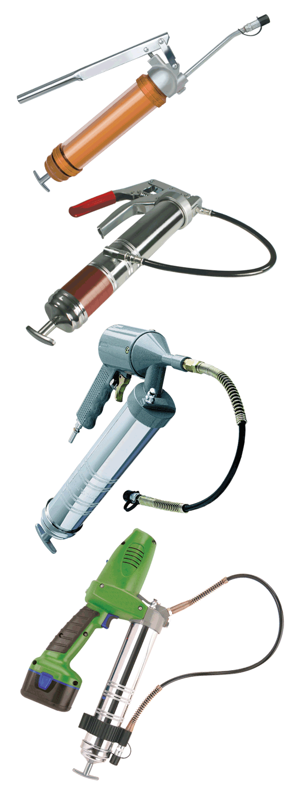
Grease guns have three ways in which they can be powered: by hand, air or electricity. Aside from these variations, the hand-powered (or manual) grease guns can either be manufactured with a lever or a pistol grip. The benefits to each of these depend primarily on the intended application and the lubrication technician’s personal preference. One other major variation to the grease gun is how the grease is to be loaded: by suction fill, cartridge or bulk.
Manual (Lever) – This is the most common type of grease gun and can supply around 1.28 grams of grease per pump, which is forced through an aperture from hand pumps.
Manual (Pistol Grip) – This variation of the lever-type grease gun allows for the one-handed pumping method, which is very common. It provides approximately 0.86 grams per pump.
Pneumatic (Pistol Grip) – This grease gun uses compressed air directed into the gun by a hose activating a positive displacement with each trigger.
Battery (Pistol Grip) – This is a low-voltage, battery-powered grease gun that works comparably to the pneumatic grease gun. It offers the advantage of being cordless.
It’s fundamental that grease is used as a lubricant because it clings to a machine’s moving surfaces without easily leaking away like oil. For this reason, the filling and refilling of grease in grease-lubricated machines must be treated differently than that of oil-lubricated machines. Therefore, it is essential that the proper grease gun operation is understood and managed by lubrication technicians for bearing and machine reliability. Simply knowing the signs of overgreasing and undergreasing and how often to reapply can go a long way in extending machinery life.
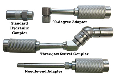
A grease gun may come with the standard connection adapter such as a hydraulic coupler, but there are several variations depending on the application. The standard hydraulic coupler is the most commonly used and most applicable. A 90-degree adapter is ideal for fittings in confined areas that require a 90-degree bend. A needle-end adapter provides a thin, precise amount of grease for tight places, while a three-jaw swivel coupler offers a variety of locking positions for different applications.
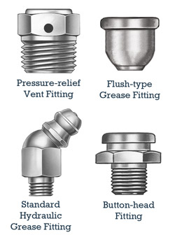
Grease fittings have several names such as a Zerk fitting, grease nipple or Alemite fitting. This is the lubrication point where the grease connector is attached. The standard hydraulic grease fitting is most commonly used for standard applications. It can be either upright or angled. The button-head fitting is ideal for good coupler engagement when large volumes of grease are being added. A flush-type grease fitting is preferred when space is limited for standard protruding fittings, while the pressure-relief vent fitting helps prevent higher pressures that could lead to damaged seals.
br />
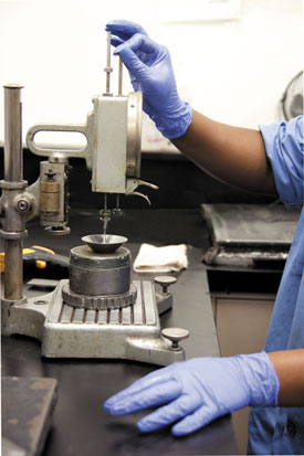
To overcome this problem, it is necessary to calculate the amount of grease that is released from a grease gun per stroke. To do this, use a calibrated scale and consistently pull 10 strokes of grease onto the scale. Once this value is known, divide by 10.
The trigger and handle are used in manual configurations of the grease gun for hand-pumping the grease from the barrel to the hose or tube in a similar way as the lever.
The barrel is the exoskeleton of the grease gun that houses either the grease tube or the grease supplied from bulk storage.
The grease tube (or cartridge) is an inserted housing of grease that is replaceable when grease is depleted.
The hydraulic coupler (or connector) is the connection point that holds the hose or fixed tube attached to the head of the grease gun.
The head of the grease gun contains grease pathways and valves that allow the pumping of grease to travel from the barrel into the flexible hose or fixed tube.
The filler nipple is the injection point for grease from a filler pump.
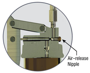
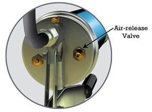
The air-release nipple allows air to escape after new grease has been added to the grease gun and pumped into the head.
The spring provides the pressure onto the plunger.
The follower rod (piston rod, barrel rod, plunger rod) helps the plunger follow a uniform path as it keeps pressure on the bottom end of the grease tube. It also acts in pulling back the spring prior to inserting a new grease tube.
The follower handle offers a grip when pulling the follower rod prior to inserting a new grease tube.
The plunger provides uniform pressure to the back end of the grease tube as grease is depleted.
The flexible hose is used interchangeably with a fixed tube for flexible positioning of the connector or coupler.
The fixed tube is a rigid form of a flexible hose.
 .
.
In this issue, the grease gun will be dissected to uncover all of its component characteristics. In addition, several other related topics will be discussed, such as common grease gun disorders, symptoms of incorrect greasing volume or frequency and best practices for using a grease gun.
Types of Grease Guns
Grease guns have three ways in which they can be powered: by hand, air or electricity. Aside from these variations, the hand-powered (or manual) grease guns can either be manufactured with a lever or a pistol grip. The benefits to each of these depend primarily on the intended application and the lubrication technician’s personal preference. One other major variation to the grease gun is how the grease is to be loaded: by suction fill, cartridge or bulk.
Manual (Lever) – This is the most common type of grease gun and can supply around 1.28 grams of grease per pump, which is forced through an aperture from hand pumps.
Manual (Pistol Grip) – This variation of the lever-type grease gun allows for the one-handed pumping method, which is very common. It provides approximately 0.86 grams per pump.
Pneumatic (Pistol Grip) – This grease gun uses compressed air directed into the gun by a hose activating a positive displacement with each trigger.
Battery (Pistol Grip) – This is a low-voltage, battery-powered grease gun that works comparably to the pneumatic grease gun. It offers the advantage of being cordless.
It’s fundamental that grease is used as a lubricant because it clings to a machine’s moving surfaces without easily leaking away like oil. For this reason, the filling and refilling of grease in grease-lubricated machines must be treated differently than that of oil-lubricated machines. Therefore, it is essential that the proper grease gun operation is understood and managed by lubrication technicians for bearing and machine reliability. Simply knowing the signs of overgreasing and undergreasing and how often to reapply can go a long way in extending machinery life.
Connectors, Adapters and Couplers
A grease gun may come with the standard connection adapter such as a hydraulic coupler, but there are several variations depending on the application. The standard hydraulic coupler is the most commonly used and most applicable. A 90-degree adapter is ideal for fittings in confined areas that require a 90-degree bend. A needle-end adapter provides a thin, precise amount of grease for tight places, while a three-jaw swivel coupler offers a variety of locking positions for different applications.
Flexible Hose vs. Fixed Tube
The decision to use a flexible hose or a fixed tube depends on the machine’s grease-fitting type and ease of location, as well as the type of grease gun used. For example, a hard-to-reach location would benefit from a flexible tube. On the other hand, lever-style grease guns require both hands to pump the grease and would favor the fixed-tube alternative.Accessories
Grease gun meters can be retrofitted onto a grease gun to help optimize lubricant consumption. Plastic caps provide benefits such as preventing corrosion and debris. They also can be color-coded so that cross-contamination does not occur. Other accessories such as sonic/ultrasonic devices are also available.Grease Fittings
Grease fittings have several names such as a Zerk fitting, grease nipple or Alemite fitting. This is the lubrication point where the grease connector is attached. The standard hydraulic grease fitting is most commonly used for standard applications. It can be either upright or angled. The button-head fitting is ideal for good coupler engagement when large volumes of grease are being added. A flush-type grease fitting is preferred when space is limited for standard protruding fittings, while the pressure-relief vent fitting helps prevent higher pressures that could lead to damaged seals.
Machine Health Risks Associated with Grease Guns
High Grease Gun Pressure
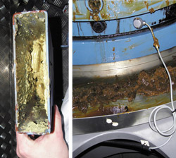
A high-pressure manual grease gun is designed to deliver from 2,000 to 15,000 psi. Applying too much pressure while greasing will damage the bearing seals, which rarely handle more than 500 psi. Symptoms of high grease gun pressure include collapsed bearing shields, damaged bearing seals, grease driven into electric motor windings, and safety and environmental issues.Regreasing Frequency
Managing regreasing frequencies to optimal conditions is necessary to avoid long-term machine health problems. If the frequency is too long, symptoms may include lubricant starvation, which promotes wear, friction and grease contamination. If the frequency is too short, excessive grease consumption and safety and environmental issues may occur.br />
Overgreasing and Undergreasing
It is important to know the exact amount of grease necessary for your greasing application to avoid overgreasing or undergreasing. Symptoms of overgreasing include damaged seals and motor windings, environmental issues, and fluid friction, which leads to increased heat generation, higher grease oxidation rates and higher energy consumption. Symptoms of undergreasing include bearing starvation, which results in friction wear and increased contamination.How Output is Measured
It is common for maintenance departments to have a wide variety of grease gun types, makes and models. This can cause grease-related disorders due to cross-contamination and inaccurate knowledge of each grease gun’s output per stroke. Grease guns are known to vary in the amount of grease that is output from 0.5 grams to more than 3 grams. This inconsistency depends on factors such as the type, model and age of the grease gun.To overcome this problem, it is necessary to calculate the amount of grease that is released from a grease gun per stroke. To do this, use a calibrated scale and consistently pull 10 strokes of grease onto the scale. Once this value is known, divide by 10.
Grease Gun Best Practices
- Calculate the proper amount of grease needed for the relubrication of bearings based upon the calibrated delivery volume of the selected grease gun.
- Use a vent plug on the relief port of the bearing to help flush old grease and reduce the risk of too much pressure on the bearing.
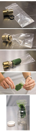
- Use extreme caution when loading grease into the grease gun to ensure that contaminants are not introduced. If using a cartridge, be careful when removing the metal lid so that no metal slivers are introduced into the grease.
- Make sure the grease gun is clearly marked to identify the grease with which it should be charged. Do not use any type of grease other than that which is identified.
- Always make sure the dispensing nozzle of the grease gun is clean before using. Pump a small amount of grease out of the dispensing nozzle and then wipe the nozzle off with a clean rag or lint-free cloth before attaching it to the grease fitting.
- Clean the grease fitting of all dirt before attaching the grease gun. Inspect and replace damaged fittings. It is helpful to use grease-fitting caps to keep them clean, but still wipe fittings clean before applying grease.
- Ensure that the proper grease is used at every grease point. Applying the wrong grease can cause an incompatibility problem, which can quickly cause bearing failure. Lubrication points should be clearly identified as to which grease is to be used. This can be done with colored labels, adhesive dots or paint markers.
- Grease guns should be stored unpressurized in a clean, cool and dry area and in a horizontal position to help keep the oil from bleeding out of the grease. Grease gun clamps make storage easy and organized. Also, cover the coupler to keep it free from dirt and contaminants.
- Calibrate grease guns regularly to ensure the proper delivery volume.
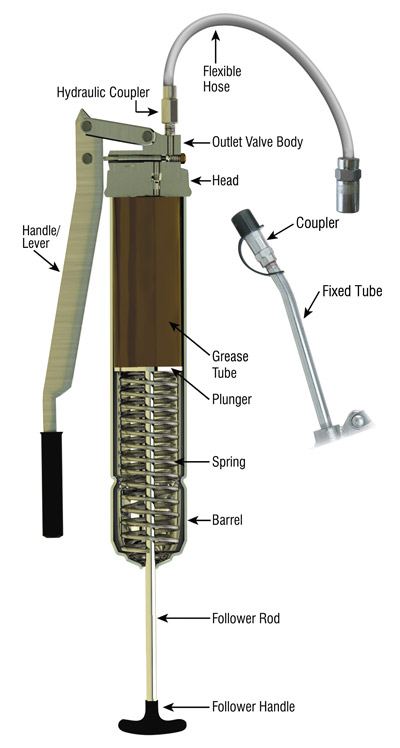
Anatomy of a Grease Gun
The lever is used in manual configurations of the grease gun for hand-pumping the grease from the barrel to the hose or tube.The trigger and handle are used in manual configurations of the grease gun for hand-pumping the grease from the barrel to the hose or tube in a similar way as the lever.
The barrel is the exoskeleton of the grease gun that houses either the grease tube or the grease supplied from bulk storage.
The grease tube (or cartridge) is an inserted housing of grease that is replaceable when grease is depleted.
The hydraulic coupler (or connector) is the connection point that holds the hose or fixed tube attached to the head of the grease gun.
The head of the grease gun contains grease pathways and valves that allow the pumping of grease to travel from the barrel into the flexible hose or fixed tube.
The filler nipple is the injection point for grease from a filler pump.
The air-release nipple allows air to escape after new grease has been added to the grease gun and pumped into the head.
The spring provides the pressure onto the plunger.
The follower rod (piston rod, barrel rod, plunger rod) helps the plunger follow a uniform path as it keeps pressure on the bottom end of the grease tube. It also acts in pulling back the spring prior to inserting a new grease tube.
The follower handle offers a grip when pulling the follower rod prior to inserting a new grease tube.
The plunger provides uniform pressure to the back end of the grease tube as grease is depleted.
The flexible hose is used interchangeably with a fixed tube for flexible positioning of the connector or coupler.
The fixed tube is a rigid form of a flexible hose.
About the Author
 Of course, greases are formulated with oil, thickener and additives. While you may be familiar with the formulation of grease, do you know what grease consistency means and how it should influence your grease selection?