http://www.machinerylubrication.com/Read/29230/condition-monitoring-machinery
Why do some machines fail early, while others operate for many additional years? Generally, eight mechanisms lead to component failures in industrial machinery: abrasion, corrosion, fatigue, boundary lubrication, deposition, erosion, cavitation and electrical discharge. These mechanisms are driven by various forces, reactive agents, the environment, temperature and time. Through monitoring the condition of your machinery and applying appropriate measurement technologies, it is possible to reveal the existence of these damaging mechanisms in order to take proactive or predictive measures and prevent failures.
4 Key Failure Mechanisms
Four wear mechanisms are commonly associated with the majority of root causes that lead to component failures of industrial machinery: abrasion, corrosion, fatigue and boundary lubrication. The latter is related to adhesion and other sliding wear modes.
Root causes and common mechanisms affecting wear of industrial machinery.
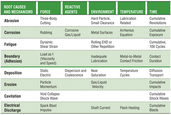
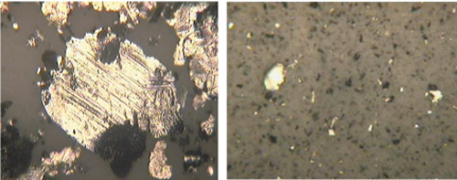
Abrasive wear particles
Abrasion
Abrasive wear is usually a result of three-body cutting wear caused by dust contamination of the lubricating oil compartment. Dust, which is much harder than steel, gets trapped at a nip point between two moving surfaces. The trapped particles tend to imbed in the relatively softer metal and then cut grooves in the harder metal. This is akin to the process by which sandpaper cuts steel. The lubricating fluid minimizes friction and adhesion, effectively improving the cutting efficiency of the abrasive particles during subsequent revolutions of the machine components.
Abrasion involves localized friction, which produces high-frequency stress waves that propagate short distances through metals. Stress-wave energy can be detected using high-frequency stress-wave analysis techniques such as Emerson’s PeakVue™ technology. Control of particle contamination in the lubricant system should be employed to remove particle debris from the system while minimizing dust ingression through air breather ports, seals and incoming lubricants. Establishing target cleanliness levels based on particle counting measurements, such as those specified in ASTM D7416, D7647 and D7596, is essential in controlling particle contamination.
Abrasive wear particles look like the cuttings often found on the shop floor under a lathe. Sometimes these particles are described as ribbons. Wear particle analysis (WPA), as guided by ASTM D7684 and using techniques explained in ASTM D7416 and D7690, can be quite effective for probing these particles. Wear particle detection and classification as defined in D7596 may also be helpful.
Corrosion
Corrosion is a chemical reaction that is accelerated by temperature. The Arrhenius rate rule suggests that chemical reaction rates double with each increase in temperature of 10 degrees C. Corrosion of metal surfaces tends to be somewhat self-limiting because metal oxide forms on surfaces to a finite depth. Oxide layers are very soft and rub away easily. Rubbing exposes underlying metal and permits deeper penetration of oxidation in the presence of oxidizing corrosive media.
Corrosive wear is typically caused by moisture or another corrosive liquid/gas. Such process acids or carboxylic acid formations may be produced during lubricant degradation due to exposure to oxygen under elevated temperatures. When these media are entrained in the lubricant, metal surfaces tend to oxidize.
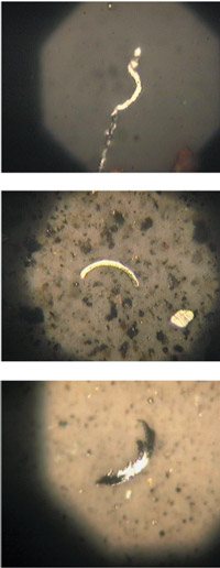
Corrosive wear particles
Sensing methods for detecting corrosive substances in oil include Karl Fischer titration, time-resolved dielectric (ASTM D7416), infrared spectroscopy, acid number (AN) and base number (BN). Corrosive wear debris in oil is best recognized using spectrometric oil analysis (SOA) such as rotrode (ASTM D6595). This is ideally suited for monitoring the expected smaller particle debris (5 microns and less) at parts-per-million quantities.
Corrosive wear debris is commonly a metal oxide, and most metal oxides are black and ultra-fine. However, sometimes reddish rust flakes can be observed. The previously described WPA techniques are appropriate for these analyses.
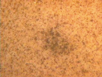
Fatigue wear particles
Fatigue
Fatigue wear is a consequence of subsurface cracking, which is caused by cumulative rolling contact loading of rollers, races and pitch lines of gear teeth. Fatigue is a work-hardening process during which dislocations migrate along slip planes through a metallic crystalline morphology. Eventually, the metallic hardening progresses to subsurface cracks accompanied by acoustic emissions like miniature earthquakes.
Fatigue moves from incipient cracking to interconnected cracks and finally to spall. This occurs when cracks intersect surfaces, allowing chunks and platelets to be carried away by the lubricating fluid. Further rolling contact produces more and larger chunks and platelets.
Acoustic emission or stress-wave analysis such as PeakVue is capable of detecting subsurface cracking that eventually produces fatigue wear. X-ray fluorescence spectroscopy (XRF) and ferrous density measurements are used to detect wear debris released into a lubricant.
When these particles are analyzed using WPA techniques, they typically look like irregular chunks or platelets. ASTM D7596-based approaches are also beneficial.
.
Boundary Lubrication (Adhesion)
Boundary lubrication is a lubrication regime in which loads are transferred by metal-to-metal contact. For most machine designs, this is abnormal because preferred lubrication methods provide a lubricant film between load-bearing surfaces. Inadequate lubrication results in boundary lubrication due to one of four reasons: no lubricant, low viscosity, excessive loading or slow speed (or a combination of these).
Normal lubrication under rolling contact is intended to produce elastohydrodynamic lubrication (EHD), which is found in “anti-friction bearings” where the fluid film is typically 1 to 5 microns thick between rollers and races. Normal lubrication for journal-type bearings produces hydrodynamic lubrication where fluid films are 50 to 100 microns thick.
When normal lubrication breaks down due to any of the four reasons listed previously, the load between moving surfaces is transferred by metal-to-metal contact, and friction rises to very high levels. Contact temperatures then become extremely high, producing melted, smeared and oxidized wear debris. Contact friction also generates high decibels of ultrasonic and audible noise.
Contact ultrasonic measurements or high-frequency stress-wave analysis techniques such as PeakVue are capable of detecting friction produced by boundary lubrication (metal-to-metal contact). Oil-breakdown-related techniques such as viscometry, time-resolved dielectric (ASTM D7416), AN and BN are also relevant in this case. Particulate can be quantified via ferrous and XRF techniques.
Fatigue wear particles, which can be captured using WPA techniques including ASTM D7596, typically demonstrate the effects of extreme temperature with evidence of metal-to-metal surface dragging.
Application-Specific Failure Mechanisms
In addition to the four principal mechanisms mentioned previously, four other mechanisms contribute to component failures in industrial machinery. These four modes are not as pervasive as abrasion, corrosion, fatigue and boundary wear, yet in particular applications, material deposition, surface erosion, cavitation and electrical discharge can be critically important.
Deposition
Deposition is different from the other failure modes because it involves material placement rather than material removal. While not a wear mechanism, adding foreign material that causes damage or plugs openings is another component failure mechanism.
Material deposition on machinery components can lead to serious problems. Materials likely to be deposited are typically transported by a gas or fluid to machine surfaces where they build up. Leading edges and other surfaces of fans and impellers tend to accumulate fibrous and particle debris transported in a liquid or gas that is being pumped. These accumulations lead to imbalance and reduced performance. Compartments frequently collect particle debris and sludge, making it very difficult to maintain system cleanliness during and after a surge in circulating oil. Control valves and other internal surfaces sometimes gather varnish deposits, which can severely impact their performance.
Wear Particle Atlas

For more information on wear debris analysis, check out the revised and expanded edition of theWear Particle Atlas.
This 192-page book offers information on the identification of various wear particle types, descriptions of wear modes that generate particles, consequences of these wear modes and an explanation of the techniques that facilitate wear particle analysis. To order online, visitstore.noria.com.
Vibration analysis is capable of non-intrusively identifying imbalance and other performance reductions caused by material deposition on rotor components. Infrared spectroscopy, patch colorimetry and cyclic voltammetry are useful approaches for detecting many issues associated with electro-chemical deposition mechanisms. Visual examination and periodic cleaning are advised for applications where debris accumulation is unavoidable, such as in air handlers and pumps. Patch testing can be utilized for observing many forms of particle, semi-solid and color body materials that may build up on surfaces and lead to varnish formation.
Erosion
Erosion occurs when material is removed due to particle impacts. Sand-blasting is an excellent example of erosion wear. Automobile owners in desert areas often coat their cars with an extra layer of clear polymer to protect the finish. Otherwise, paint is quickly removed, exposing bare metal on hoods and fenders.
The simplest form of condition monitoring is optically identifying a cloud of debris being forcefully propelled by fluid media into a solid surface. Visual examination is a recommended means of detecting evidence of erosion. It generally is impractical to perform wear particle analysis for wear caused by erosion because the volume of solid matter causing erosion is overwhelming.
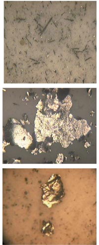
Severe sliding wear particles
Cavitation
Cavitation wear is commonly experienced on the back side of impellers. A low-pressure vacuum creates voids or bubbles in a liquid, which collapse when pressure returns. The fluid then speeds up to fill the voids. As the fluid fills the collapsing voids, it accelerates to supersonic speeds, and shock waves cause material damage to the back side of the impeller. Damage kicks away material, leaving pits in the surface.
Acoustic emission and stress-wave analysis such as PeakVue are capable of identifying cavitation. However, debris analysis is unlikely to detect impeller damage due to cavitation. Therefore, it is recommended that impellers be visually inspected at opportune intervals to look for signs of cavitation and other evidence of physical deterioration.
Electrical Discharge
Electric motors sometimes produce shaft currents, where current travels along a length of a shaft, across a bearing fluid-film thickness and back through the machinery housing to the ground. Typically, the lubricant film boundary is approximately 1 micron thick for roller bearings and 50 microns thick for journal bearings.
Lubricants are good insulating “dielectric” fluids. Electrical discharges arc across the fluid-film gaps striking metal surfaces on both sides and creating surface damage under intense heat and shock of microscopic electrical arc blasts. In roller bearings, this process is sometimes called “fluting” due to a symmetrical pattern related to the roller positions under repeated electrical discharge.
Shaft currents can be identified electrically using a sensitive machinery analyzer or multimeter to detect current passing from the ground through a metal brush contacting the rotating shaft. Electrical discharge blasts may be recognized using acoustic emission or a stress-wave measurement technique such as PeakVue.
Electrical discharge particles are typically ejected as molten metal, which solidifies into spherical “welding slag” with a black, partially oxidized surface. Unlike welding slag, which usually is 50 to 100 microns in size, these particles can be relatively small.
Combining Vibration and Oil Analysis
To effectively monitor rotating machinery at industrial plants, it is advisable to combine vibration and oil analysis techniques. Vibration analysis covers a range of proactive measurements, including resonance, looseness, misalignment, imbalance, incorrect assembly and transient operation through startup or coast down. Oil analysis is uniquely suited for proactive measurements such as the testing of incoming lubricants, contamination control, measuring water and dust in oil, and determining when oil is deteriorated or unfit for use.
Together, oil analysis and vibration analysis provide complementary predictive assessments for machine wear and the state of component failure along a progression from incipient to near catastrophic.
No comments:
Post a Comment